Users Online
· Members Online: 0
· Total Members: 188
· Newest Member: meenachowdary055
Forum Threads
Latest Articles
Articles Hierarchy
#4_05 Using IOT for RFID and MQTT and the Raspberry Pi
Using IOT for RFID and MQTT and the Raspberry Pi
Chapter Goal: Build an IOT device for Reading RFID Tags on Various Packages
Topics Covered in this Chapter:
-
Introduction to MQTT Publish / Subscribe Systems and Servers
-
Connecting your RFID Reader to your MQTT Raspberry Pi Server
The world of IOT is dominated by small computers having small amounts of resources and power to communicate information with the rest of the world. MQTT is a publish-subscribe, lightweight protocol for IOT devices to communicate with the server and through the server, with each other. MQTT is also available for “mesh”-type networks, like Zigbee, that allow device-to-device communication. RFID (Radio Frequency IDentification) is an inexpensive way of reading uniquely numbered cards and tags via radio waves from short distances. RFID and its cousin, NFC (Near Field Communications) are showing up in more and more applications.
In this chapter, we build an RFID device and then connect through an MQTT publisher to an MQTT broker as in Chapter 5, but with the difference that we are replacing the IBM Bluemix MQTT broker with a Mosquitto broker running on a $20 Raspberry Pi.
IOT Characterization of This Project
As we discussed in Chapter 1, the first thing to do to understand an IOT project is to look at our six different aspects of IOT. ITORFID is a simpler project than our other four projects, but the dataflow is much more complex.
Table 6-1 characterizes different aspects of the project. Ratings are from 1–10, 1 being the least suitable for IOT and 10 being the most suitable for IOT applications. This gives us a CPLPFC rating of 8.3. Great for learning and experimenting, and it could be deployed for some market applications.
Table 6-1. IOT Characterization of the Project
|
Aspect |
Rating |
Comments |
|
Communications |
9 |
WiFi connection to Internet - |
|
Processor Power |
9 |
80MHz XTensa Harvard Architecture CPU, ∼80KB Data RAM / ∼35KB of Instruction RAM / 200K ROM |
|
Local Storage |
8 |
4MB Flash (or 3MB file system!) |
|
Power Consumption |
8 |
∼200mA transmitting, ∼60mA receiving, noWiFi ∼15mA, Standby ∼1mA |
|
Functionality |
7 |
Partial Arduino Support (limited GPIO/Analog Inputs) |
|
Cost |
9 |
< $12 and getting cheaper |
Note that the power consumption in this application could be dramatically reduced by adding a power down mode, say after 5 minutes of not using the RFID Reader.
What Is RFID Technology?
Radio Frequency Identification (RFID) is the use of radio waves to transfer data, specifically in the area of identifying and tracking tags attached to objects, people, and animals. Often the RFID Tag has no power supply and is activated and powered by radio waves beamed at the RFID Tag. This technology goes back to the 1940s and was first demonstrated by Theremin in the Soviet Union. Interestingly enough, he used this technology to put a covert listening device in the United States Embassy conference room in 1946. It was used for six years when in 1952, it was discovered that the seal contained a microphone and a resonant cavity that could be stimulated from an outside radio signal. While this used a resonant cavity that changed its shape when stimulated by sound waves, and hence modulated a reflected radio wave beamed at the unit, it is considered a predecessor to RFID technology.
[en.wikipedia.org/wiki/The_Thing_(listening_device)]
RFID tags can be active, passive (no battery power - we are using this technology in this chapter), and battery assisted passive. A passive tag contains no battery, instead using the radio energy transmitted by the RFID Reader. To operate a passive tag, it needs to be hit with a power level roughly one thousand times greater than the resulting signal transmissions.
When an RFID Tag is hit by a beam of radio waves from a transmitter, the passive tag is powered up and transmits back the tag identification number and other information. This may be a unique serial number, a stock or lot number, or other specific information. Since tags have unique numbers, the RFID system can read multiple tags simultaneously, with some clever programming of the receiver and transmitter.
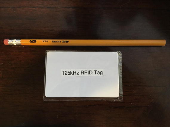
There are a number of different RFID standards in common use. There are three standards for putting ID chips in pets, which of course are not compatible with each other and require different readers. The short-range tags we are using in this chapter operated at the low frequency of 125kHz and can go up to 100mm (Figure 6-1). Other tags can be picked up (with active RFID technology) up to 100 meters.
Figure 6-1.125kHz Card-Shaped RFID Tag
While RFID and NFC technologies are designed for short distance use, the addition of a large power transmitter and a large antenna can change the meaning of “short distance.”
What Is MQTT?
In Chapter 5, we used an MQTT publisher module to talk to the IBM MQTT broker at IBM Bluemix.
To refresh the reader’s memory, MQTT is a publish-subscribe-based “light weight” messaging protocol for use on top of the TCP/IP protocol, such as the WiFi packets that we are using in this project. It is designed for connections with remote locations where a “small code footprint” is required or the network bandwidth is limited.
Publish-subscribe is a pattern where senders of messages, called publishers (in this case our project IOTRFID is the publisher), don't program the messages to be sent directly to subscribers, but instead characterize message payloads into classes.
You can think of it as writing stories for a newspaper where you don’t know who will be subscribing to the article.
Hardware Used for IOTRFID
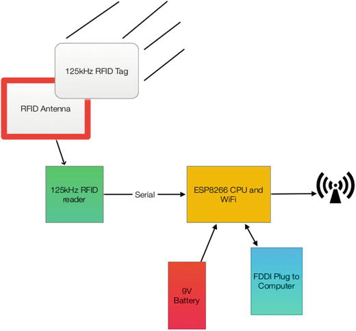
There are there major parts to the hardware from the IOTRFID (Figure 6-2). The first is the ESP8266 Adafruit Huzzah that we have seen in previous chapters.
Figure 6-2.Block Diagram of IOTRFID
The RFID reading circuit is a small inexpensive board from Seeedstudio in China. The key reason this board was chosen was the fact it works on 3.3V (which is the same as the ESP8266) and requires no external components (well, yes, it does require an antenna that is included).
We also purchased a 125KHz RFID Tag from SparkFun. Be careful of the RFID Tag you buy. Not all are compatible.
Building an MQTT Server on a Raspberry Pi
As described in Chapter 5, MQTT requires a message broker. The design pattern is this:
|
1. |
|
|
|
2. |
|
|
|
3. |
Raspberry Pi MQTT broker disseminates to all subscribing objects (which may be different processes in the same machine - as in our case - or even different machines entirely. |
|
In Chapter 5, we used the IBM Bluemix as the message broker. In the IOTRFID project we are going to build a message broker on the Raspberry Pi.
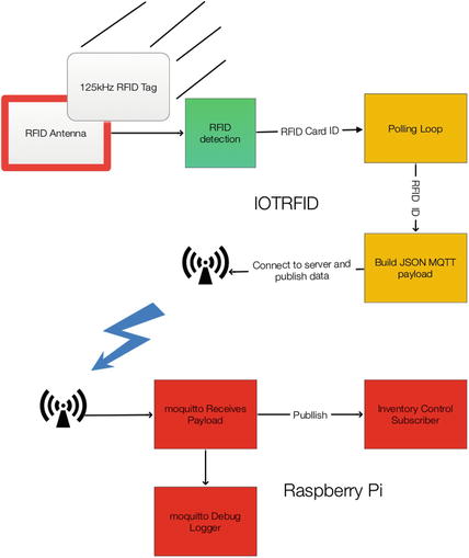
Figure 6-3 shows the dataflow in the entire application - including the Raspberry Pi. The dataflow in this application is basically one way: from the RFID Tag to the Raspberry Pi mosquitto server. Note, however, there are two channels available over the WiFi and you could send commands back to the IOTRFID project telling the user information about the part being inventoried. For example, you could display the destination for the box or the expiration date.
Figure 6-3.Dataflow of Complete System
There are a number of MQTT brokers available for different machines. For this project, we have selected one of the most popular and stable brokers, “Mosquitto.” Note the two “t”’s in Mosquitto. The bane of spell checkers everywhere.
Mosquitto supports MQTT v3.1/3.1.1 and is easily installed on the Raspberry Pi and somewhat less easy to configure. Next we step through installing and configuring the Mosquitto broker.
The Software on the Raspberry Pi
We start by setting up the software on the Raspberry Pi. We do this so our IOTRFID has something to talk to when we set turn the IOTRFID on.
Installing the MQTT “Mosquitto”
Unfortunately, the Raspberry Pi normal “apt-get” archives do not contain the latest version of the Mosquitto software. If you don’t install the latest version of the broker, you will get odd errors (because of version compatibility errors) and it will not work. So, the first thing is to open a Terminal window (or log in using ssh) to your Raspberry Pi and do the following:
sudo wget http://repo.mosquitto.org/debian/mosquitto-repo.gpg.key
sudo apt-key add mosquitto-repo.gpg.key
cd /etc/apt/sources.list.d/
sudo wget http://repo.mosquitto.org/debian/mosquitto-wheezy.list
sudo apt-get update
sudo apt-get install mosquitto
Next we can install the three parts of Mosquitto proper.
Execute the following command to install these three parts:
sudo apt-get install mosquitto mosquitto-clients python-mosquitto
As is the case with most packages from Debian, the broker is immediately started. Since we have to configure it first, stop it:
sudo /etc/init.d/mosquitto stop
Configuring and Starting the Mosquitto Server
Before using Mosquitto, we need to set up the configuration file. The configuration file is located at /etc/mosquitto.
sudo nano /etc/mosquitto/mosquitto.conf
# Place your local configuration in /etc/mosquitto/conf.d/
#
# A full description of the configuration file is at
# /usr/share/doc/mosquitto/examples/mosquitto.conf.example
pid_file /var/run/mosquitto.pid
persistence true
persistence_location /var/lib/mosquitto/
log_dest file /var/log/mosquitto/mosquitto.log
include_dir /etc/mosquitto/conf.d
Change the “log_dest” line to:
This puts the logging information as a “topic” so we can subscribe to it later on to see what is going on in our IOTRFID system.
Next add the following six lines:
log_type warning
log_type notice
log_type information
connection_messages true
log_timestamp true
Now your /etc/mosquitto.conf files should look like this:
# Place your local configuration in /etc/mosquitto/conf.d/
#
# A full description of the configuration file is at
# /usr/share/doc/mosquitto/examples/mosquitto.conf.example
pid_file /var/run/mosquitto.pid
persistence true
persistence_location /var/lib/mosquitto/
log_dest topic
log_type error
log_type warning
log_type notice
log_type information
connection_messages true
log_timestamp true
include_dir /etc/mosquitto/conf.d
Starting the Mosquitto Server
Now start the mosquitto server:
sudo /etc/init.d/mosquitto start
The server should start, and you are ready to move on to testing.
Testing the Mosquitto Server
Open up two more terminal windows.
mosquitto_sub -d -t hello/world
mosquitto_pub -d -t hello/world -m "Hello from Terminal window 2!"
When you have done the second statement you should see this in the Terminal 1 window.
∼ $ sudo mosquitto_sub -d -t hello/world
Client mosqsub/3014-LightSwarm sending CONNECT
Client mosqsub/3014-LightSwarm received CONNACK
Client mosqsub/3014-LightSwarm sending SUBSCRIBE (Mid: 1, Topic: hello/world, QoS: 0)
Client mosqsub/3014-LightSwarm received SUBACK
Subscribed (mid: 1): 0
Client mosqsub/3014-LightSwarm received PUBLISH (d0, q0, r0, m0, 'hello/world', ... (32 bytes))
Greetings from Terminal window 2
Now you are running the Mosquitto broker successfully.
Next, let’s build the IOTRFID device.
Building the IOTRFID
The IOTRFID project consists of four major parts:
The purpose of this project is to prototype an inventory control system that uses RFID tags. The ESP8266 controls the RFID Reader and reports the RFID Tag to the Raspberry Pi server. We then use MQTT through the WiFi interface on the ESP8266 to send the inventory information to the Raspberry Pi. The Raspberry Pi could then use the RFID information to work with a database, alert the end customer, etc.
The Parts Needed
The IOTRFID can be assembled for about $35 from the sources in Table 6-2.
Table 6-2. Parts List for IOTRFID
|
Part Number |
Count |
Description |
Approximate Cost per Board |
Source |
|
ESP8266 Huzzah Board |
1 |
CPU / WiFi board |
$10 |
|
|
Mini 125kHz RFID Reader |
1 |
125kHz RFID Serial Reader |
$11 |
www.seeedstudio.com/depot/Mini-125Khz-RFID-Module-External-LEDBuzzer-Port-70mm-Reading-Distance-p-1724.html |
|
125kHz RFID Tags |
1 |
RFID Tag compatible with Mini 125kHz RFID Reader |
$2 |
|
|
FTDI Cable |
1 |
Cable for programming the ESP8266 from PC/Mac |
$11 |
www.switchdoc.com/inexpensive-ftdi-cable-for-arduino-esp8266-includes-usb-cable/ |
Installing Arduino Support on the PC or Mac
Once again, the key to making this project work is the development software. While there are many ways of programming the ESP8266 (MicroPython [ https://micropython.org ], NodeMCU Lua interpreter [ http://nodemcu.com ] and the Arduino IDE (Integrated Development Environment) [ https://www.arduino.cc/en/Main/Software ]), we chose the Arduino IDE for its flexibility and the large number of sensors and device libraries available.
To install the Arduino IDE you need to do the following:
|
1. |
Download the Arduino IDE package for your computer and install the software [ https://www.arduino.cc/en/Guide/HomePage ] . |
|
|
2. |
Download the ESP libraries so you can use the Arduino IDE with the ESP breakout board. Adafruit has an excellent tutorial for installing the ESP8266 support for the Arduino IDE [https://learn.adafruit.com/adafruit-huzzah-esp8266-breakout/using-arduino-ide ]. |
|
The Hardware
The main pieces of hardware in the swarm device are these:
The ESP8266 communicates with the Raspberry Pi by using the WiFi interface. The ESP8266 uses a serial interface to communicate with the light sensor. The WiFi is a standard that is very common. The serial interface used is one wire (Tx line on the RFID Reader to Rx on the ESP8266 - Pin GPIO #4 on the ESP8266). In a serial interface, one bit at a time is sent along with stop and start bits for each byte. The data is sent at 9600 baud, which is an old way of saying about 9600 bits per second.
What Is This Sensor We Are Using?
The Mini 125kHz RFID Reader is a simple, inexpensive 125kHz RFID Tag reader with a range of about 70mm. Note that the range for a reader like this is set by a combination of the output power of the reader and the antenna design.
If you have a bigger antenna and more power, you can read RFID tags at a much larger distance. A quick check on the Web showed the record for passive 125kHz RFID tags is around 10 or 15 meters. Better antennas that are focused on a beam could do even better than this. Don’t assume that someone cannot read the cards in your wallet if they really wanted to do that.
3D Printed Case
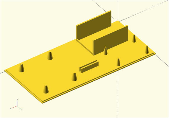
The 3D printed case for this project has a holder for a 9 volt battery, pylons to hold the antenna in place, a slot to mount the RFID Reader board, and pylons for the ESP8266. The code is for OpenSCAD, a free 3D CAD system that appeals to programmers. Figure 6-4 shows the 3D printed case with pylons for mounting the boards.
Figure 6-4.3D Printed Case for the IOTRFID Project
The following OpenSCAD code builds the mounting base step by step by merging basic shapes such as cubes and cones. We also build a stand to keep the battery from sliding across the base.
// IOT IOTFRFID Mounting Base
//
// SwitchDoc Labs
// February 2016
//
union()
{
cube([130,60,2]);
translate([-1,-1,0])
cube([132,62,1]);
// Mount for Battery
translate([-30,0,0])
union ()
{
translate([40,2,0])
cube([40,1.35,20]);
translate([40,26.10+3.3,0])
cube([40,1.5,20]);
// lips for battery
translate([79,2,0])
cube([1,28,4]);
// plyons for ESP8266
translate([70-1.0,35,0])
cylinder(h=10,r1=2.2, r2=1.35/2, $fn=100);
translate([70-1.0,56,0])
cylinder(h=10,r1=2.2, r2=1.35/2, $fn=100);
translate([70-34,35,0])
cylinder(h=10,r1=2.2, r2=1.35/2, $fn=100);
translate([70-34,56,0])
cylinder(h=10,r1=2.2, r2=1.35/2, $fn=100);
}
// stand for board
translate([15,40,0])
union ()
{
translate([40,2,0])
cube([20,1.35,7]);
translate([40,3.55+1.35,0])
cube([20,1.35,7]);
}
// plyons for RFID board
translate([50,0,0])
union()
{
translate([33+36.0,10,0])
cylinder(h=10,r1=3.2, r2=2.40/2, $fn=100);
translate([33+36.0,50,0])
cylinder(h=10,r1=3.2, r2=2.40/2, $fn=100);
translate([36,10,0])
cylinder(h=10,r1=3.2, r2=2.40/2, $fn=100);
translate([36,50,0])
cylinder(h=10,r1=3.2, r2=2.40/2, $fn=100);
}
}
The Full Wiring List
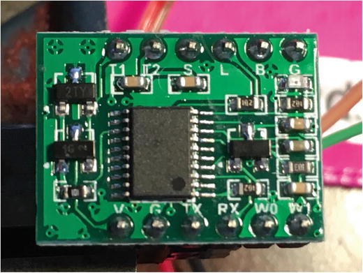
Figure 6-5 shows the back of the Mini 125kHz RFID Reader to clearly display the pin labels on the back of the board.
Figure 6-5.Closeup of Mini RFID Board
Following is the complete wiring list for the IOTRFID project. As you wire it, check off each wire for accuracy.
The Key for Table 6-3 is below. Table 6-3 contains all the wiring information for building the IOTRFID. Follow it closely to make your project work the first time. This table contains all of the individual wiring connections to complete the project.
Mini 125kHz RFID Reader: RFIDBoard
Table 6-3.Wiring List for the IOTRFID Project
|
ESP8266 Huzzah Board (ESP8266) |
|
|
|
|
From |
To |
Description |
|
|
ESP8266 / GND |
RFIDBoard /G |
Ground for RFID Reader board |
|
|
ESP8266 / 3V |
RFIDBoard /V |
3.3V Power for RFID Board |
|
|
ESP8266 / #5 |
RFIDBoard /Rx |
RFID Board Receiver (not used in this project) |
|
|
ESP8266 / #4 |
RFIDBoard /Tx |
RFID Board Serial Transmitter |
|
|
ESP8266 / GND |
9VBat / “-” terminal (minus terminal) |
Ground for battery |
|
|
ESP8266 / VBat |
9VBat / “+” terminal (plus 9V) |
9V from battery |
|
|
RFIDBoard / T1 |
RFID Antenna JST2 Plug |
Lead from Antenna - Push plug over T1 and T2 - order doesn’t matter |
|
|
RFIDBoard / T2 |
RFID Antenna JST2 Plug |
Lead from Antenna - Push plug over T1 and T2 - order doesn’t matter |
|
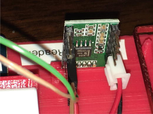
Figure 6-6 shows the JST2 Plug pushed over the two pins on the RFID board connecting the RFID board with the Antenna.
Figure 6-6.Closeup of RFID Antenna JST2 Plug
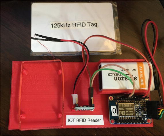
Your completed IOTRFID project should look similar to Figure 6-7.
Figure 6-7.The Completed IOTRFID Project
The Software for the IOTRFID Project
No computer-based project is complete without the software to make the computer and board perform the functions designed. The main code IOTRFID is very short and makes good use of existing libraries.
The Libraries
In this project, we are using two libraries. Because we didn’t have to modify the libraries to make them work with the ESP8266, we have not reproduced them here. The two libraries are the following:
seeedRFID - The library for interfacing the ESP8266 to the RFID Reader. Basically a simple shell around the SoftSerial Arduino libraries. [ https://github.com/Seeed-Studio/RFID_Library ]
PubSubClient - A simple client for MQTT. This is a very usable and well-documented library. We use this library to talk to the MQTT server (mosquitto) on the Raspberry Pi. [ http://pubsubclient.knolleary.net ]
The Main Software
The ESP8266 Arduino IDE software for this project is relatively straightforward. You will see some similarities to the IBM Bluemix software in the last chapter. The main difference is that you are now doing both ends of the MQTT connections. Remember to put your own WiFi access point and password in the code as well as entering the IP address of your Raspberry Pi.
The general flow of the software consists of first initializing the WiFi connection and the RFID hardware and then going into a loop, checking for RFID Tag events.
SwitchDoc Labs Code for IOT RFID
IOT RFID uses publish subscribe to communicate to Raspberry Pi
January 2016
*/
// BOF preprocessor bug prevent - insert on top of your arduino-code
#if 1
__asm volatile ("nop");
#endif
// Board options
#pragma GCC diagnostic ignored "-Wwrite-strings"
extern "C" {
#include "user_interface.h"
}
#include <ESP8266WiFi.h>
#include "PubSubClient.h"
#include "seeedRFID.h"
#define RFID_RX_PIN 4
#define RFID_TX_PIN 5
#undef TEST
SeeedRFID RFID(RFID_RX_PIN, RFID_TX_PIN);
RFIDdata tag;
int count = 0; // counter for buffer array
// Variables
int blinkPin = 0; // pin to blink led at each reception of RFID code
#include "Utils.h"
//----------------------------------------------------------------------
//Local WiFi Variables
const char* ssid = "YOURWIFIACCESSPOINT";
const char* password = "YOURWIFIPASSWORD";
#define IOTRFIDVERSION 005
// Raspberry Pi Information
#define ORG "switchdoc"
#define DEVICE_TYPE "IOTRFID-01"
#define DEVICE_ID "1"
#define TOKEN "ul!fjH!y8y0gDREmsA"
// setup for IOT Raspberry Pi
char server[] = "192.168.1.40"; // Replace with YOUR RASPBERRY IP Number
char topic[] = "IOTRFID";
char authMethod[] = "use-token-auth";
char token[] = TOKEN;
char clientId[] = "IOTRFID";
void callback(char* topic, byte* payload, unsigned int length) {
Serial.println("callback invoked from IOT RFID");
}
WiFiClient wifiClient;
PubSubClient client(server, 1883, callback, wifiClient);
void setup() {
// put your setup code here, to run once:
pinMode(0, OUTPUT);
Serial.begin(9600); // we agree to talk fast!
Serial.println("----------------");
Serial.println("IOTRFID publish/subscribe Inventory");
Serial.println("----------------");
// signal start of code - three quick blinks
blinkLED(3, 250);
Serial.print("Connecting to WiFi ");
if (strcmp (WiFi.SSID().c_str(), ssid) != 0) {
WiFi.begin(ssid, password);
}
while (WiFi.status() != WL_CONNECTED) {
delay(500);
Serial.print(".");
}
Serial.println("");
Serial.print("Local WiFi connected, IP address: ");
Serial.println(WiFi.localIP());
blinkLED(5, 500);
}
void loop() {
// put your main code here, to run repeatedly:
count = 0;
if (!!!client.connected()) {
Serial.print("Reconnecting client to ");
Serial.println(server);
while (!!!client.connect(clientId)) {
Serial.print(".");
delay(500);
}
Serial.println();
}
// Check for RFID available
String payload;
if (RFID.isAvailable())
{
tag = RFID.data();
Serial.print("RFID card number read: ");
Serial.println(RFID.cardNumber());
#ifdef TEST
Serial.print("RFID raw data: ");
for (int i = 0; i < tag.dataLen; i++) {
Serial.print(tag.raw[i], HEX);
Serial.print('\t');
}
#endif
// Sending payload
payload = "{\"d\":{\"IOTRFID\":\"IR1\",";
payload += "\"VER\":\"";
payload += IOTRFIDVERSION;
payload += "\",\"RFID_ID\":\"";
payload += String(RFID.cardNumber());
payload += "\"";
payload += "}}";
// check for message
Serial.println(payload.length());
count = 0;
if (payload.length() >= 53) // good message
{
Serial.print("Sending IOTRFID payload: ");
Serial.println(payload);
if (client.publish(topic, (char*) payload.c_str())) {
Serial.println("IOTRFID Publish ok");
blinkLED(1, 500);
} else {
Serial.println("IOTRFID Publish failed");
blinkLED(2, 500);
}
}
else
{
delay(500);
}
}
yield(); // This is necessary for the ESP8266 to do the background tasks
}
Testing the IOTRFID System
Using the Arduino IDE, flash the ESP8266 with the IOTRFID software above.
After it has been flashed, you should see the following on the Arduino serial monitor:
IOTRFID publish/subscribe Inventory
----------------
Connecting to WiFi ......
Local WiFi connected, IP address: 192.168.1.135
Reconnecting client to 192.168.1.40
Leave the IOTRFID running for now.
Setting Up the Mosquitto Debug Window
Go back into Terminal window 1 from earlier in the chapter and hold down the control key and click “c” (control-c) to kill the running process from the previous step. If you had closed it, open up another Terminal window and following the instructions below.
Build a python file for our debug and logging subscription to the Mosquitto broker:
# SwitchDoc Labs
#
# Display logging subscription
#
# January 2016
#
import paho.mqtt.client as mqtt
# The callback for when the client receives a CONNACK response from the server.
def on_connect(client, userdata, flags, rc):
print("Connected with result code "+str(rc))
# Subscribing in on_connect() means that if we lose the connection and
# reconnect then subscriptions will be renewed.
client.subscribe("$SYS/broker/log/#");
# The callback for when a PUBLISH message is received from the server.
def on_message(client, userdata, msg):
print(msg.topic+" "+str(msg.payload))
client = mqtt.Client()
client.on_connect = on_connect
client.on_message = on_message
client.connect("localhost", 1883, 60)
# Blocking call that processes network traffic, dispatches callbacks and
# handles reconnecting.
# Other loop*() functions are available that give a threaded interface and a
# manual interface.
client.loop_forever()
Then run the code by typing this:
sudo python IOTRFIDLogSubscribe.py
We use “sudo” to make sure that python is running with root privileges to avoid any potential permissions issues.
If you left your IOTRFID running, you will see this:
SYS/broker/log/N 1454535157: Client IOTRFID has exceeded timeout, disconnecting.
$SYS/broker/log/N 1454535157: Socket error on client IOTRFID, disconnecting.
$SYS/broker/log/N 1454535157: New connection from 192.168.1.135 on port 1883.
$SYS/broker/log/N 1454535157: New client connected from 192.168.1.135 as IOTRFID (c1, k15).

