Users Online
· Members Online: 0
· Total Members: 188
· Newest Member: meenachowdary055
Forum Threads
Latest Articles
Articles Hierarchy
#4_02 Building a Solar Powered IOT Weather Station
Building a Solar Powered IOT Weather Station
Chapter Goal: Gathering Data and Transmission of Data across the Internet
Topics Covered in This Chapter:
-
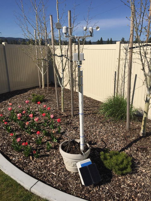
How to build a solar powered IOT Weather System (Figure 3-1 )
Figure 3-1.Overall Picture of Station
Everybody talks about the weather. In this chapter, we are going to talk about the weather in much more detail than just the temperature.
In the previous chapter, we looked at building simple IOT devices that would measure temperature and share that information with a server and other IOT devices. It was a simple application, but still illustrated a number of important concepts. In this chapter, we are building a much more complex and flexible project based on using the Raspberry Pi as part of the IOT device.
The IOTWeatherPi not only gathers thirteen different types of weather data, it also monitors and reports its own state, status, and health.
IOT Characterization of This Project
As I discussed in Chapter 1, the first thing to do to understand an IOT project is to look at our six different aspects of IOT. IOTWeatherPi is a complex product, but Table 3-1 breaks it down into our six components .
Table 3-1.IOTWeatherPi Characterization (CPLPFC)
|
Aspect |
Rating |
Comments |
|
Communications |
9 |
WiFi connection to Internet - can do AdHoc mesh-type communication and Bluetooth |
|
Processor Power |
7 |
Raspberry Pi A+ / 256Mb RAM |
|
Local Storage |
8 |
8GB of SD Card |
|
Power Consumption |
2 |
∼200mA consumption - Not reasonable for small batteries |
|
Functionality |
8 |
Full Linux-based system. MySQL, etc. |
|
Cost |
2 |
Expensive for many applications. Board is ∼$25 |
Ratings are from 1–10, 1 being the least suitable for IOT and 10 being the most suitable for IOT applications. This gives us a CPLPFC rating of 6. Great for learning, not so good for deployment for most applications.
No doubt about it, the Raspberry Pi is a very flexible and powerful IOT platform. However, the power consumption, cost, and physical size of the device make it more suitable for prototyping or for stand-alone, highly functional IOT units.
How Does This Device Hook Up to the IOT?
With IOTWeatherPi, we have a lot of options. We can hook up to the Internet using the WiFi connector. We can use the Bluetooth to hook up to local devices and we can also use the WiFi in AdHoc mode to make local connections. In this chapter, we will be using the WiFi interface to talk to the wider world of IOT devices.
Data Gathering
The IOTWeatherPi uses thirteen different sensors to detect weather connections. Because I am using a Raspberry Pi and have good storage mechanisms and disk space, I use a MySQL database to store all the weather data for future analysis and download. We also use MatPlotLib to build graphs and use an iOS App called RasPiConnect to display the information across the Internet.
The Project - IOTWeatherPi
WeatherPi is a solar powered Raspberry Pi WiFi connected weather station designed for use in the IOT by the author’s company. This is a great system to build and tinker with. All of it is modifiable and all source code is included. Following are the most important functions :
-
Has a full database containing history of the environment (MySQL)
-
Monitors and reports data on the solar powered system - great for education!
-
Can be modified to do SMS (Text) messaging, Twitters, web pages, and more
-
Can connect to the IOT via Twitter, texting, e-mail, and WiFi
This chapter will show you how to build a WiFi Solar Powered Raspberry Pi Weather Station. This project grew out of a number of other projects, including the massive Project Curacao [ www.switchdoc.com/project-curacao-introduction-part-1/ ], a solar powered environmental monitoring system deployed on the Caribbean tropical island of Curacao. Project Curacao was written up in an extensive set of articles in MagPi magazine (starting in Issue 18 and continuing through Issue 22).
The IOTWeatherPi Solar Powered Weather Station is an excellent education project. There are many aspects of this project that can be looked at and analyzed for educational purposes:
-
How do solar power systems behave? Limitations and advantages.
-
Shutting down and starting up small computers on solar power.
-
Add your own sensors for UV, dust and pollen count, and light color.
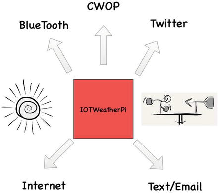
Figure 3-2 shows how IOTWeatherPi is connected to the IOT while Figure 3-3 describes all the major blocks in the project.
Figure 3-2.Block Diagram of WeatherPi and the IOT
Figure 3-3.Block Diagram of IOTWeatherPi
How This All Works
The IOTWeatherPi Block Diagram looks a lot more complicated than it actually is.
The first thing to notice is that the dashed lines are individual boards (WeatherPiArduino and SunAirPlus), which contain a lot of the block diagram; and the second thing is that all of the sensors to the left of the diagram plug into the WeatherPiArduino board, which simplifies the wiring. Don't be intimidated!
The Subsystems
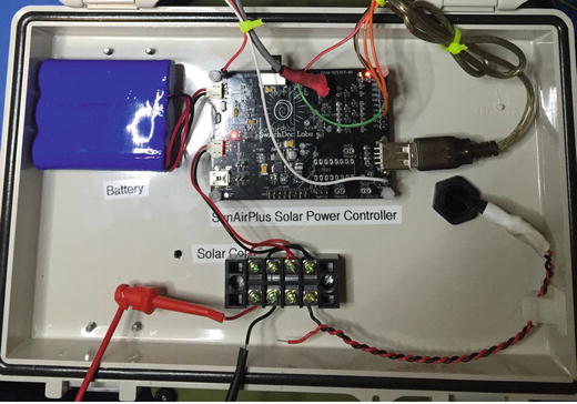
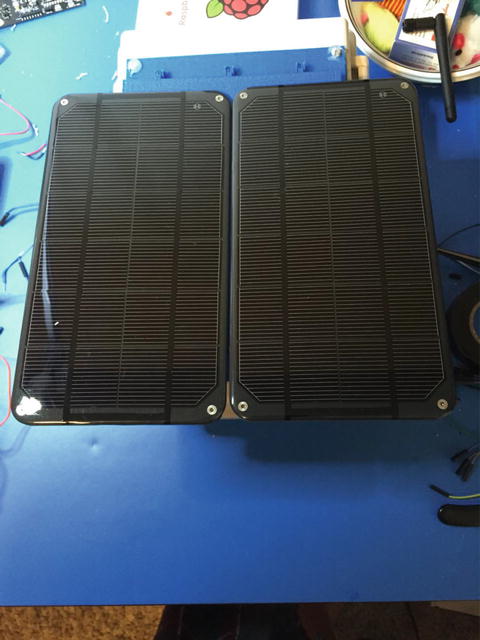
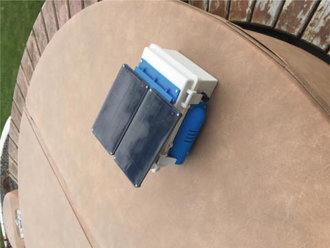
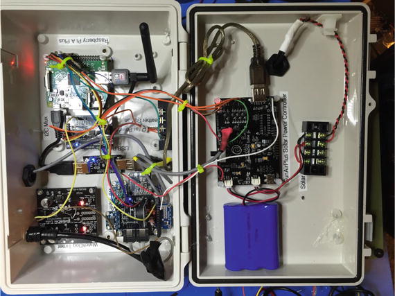
The Power Subsystem of IOTWeatherPi uses a SunAirPlus [ www.switchdoc.com/sunairplus-solar-power-controllerdata-collector/ ] Solar Power Controller that handles the solar panels, charging of the battery, and then supplies the 5V to the Raspberry Pi and the rest of the system. It also contains sensors that will tell you the current and voltage produced by the Solar Panels and consumed by the batteries and the Raspberry Pi. Gather that Data! Figure 3-4 shows the solar charger board and the battery pack mounted in the top of the enclosure. Figure 3-5 shows the solar cells on the top of outside of the enclosure .
Figure 3-4.Solar Power Controller
Figure 3-5. Solar Cells
It also contains the hardware watchdog timer and the USB PowerControl that actually shuts off the power to the Raspberry Pi during a brownout event (after the Pi shuts gracefully down under software control).
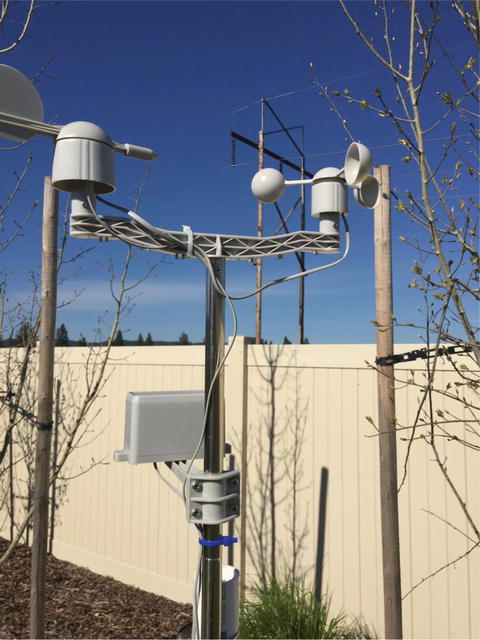
The Sensor Subsystem of IOTWeatherPi uses a WeatherPiArduino [ www.switchdoc.com/weatherpiarduino-bare-board/ ] as the base unit and then plugs in a bunch of optional sensors such as wind speed / direction / rain, lightning detection (how cool is that!), inside and outside temperature, and humidity. Figure 3-6 pictures the wind and rain sensors.
Figure 3-6.Wind / Rain Sensors
The Software Subsystem of IOTWeatherPi runs in Python on the Raspberry Pi. It collects the data, stores in in a MySQL database, builds graphs, and does housekeeping and power monitoring.
The IOTWeatherPi Sensor Suite senses the following environmental values:
You can add more to the I2C bus and Analog to Digital Converter such as UV, dust counts, light color (sensing some types of pollution), and more! It's a great platform for expansion.
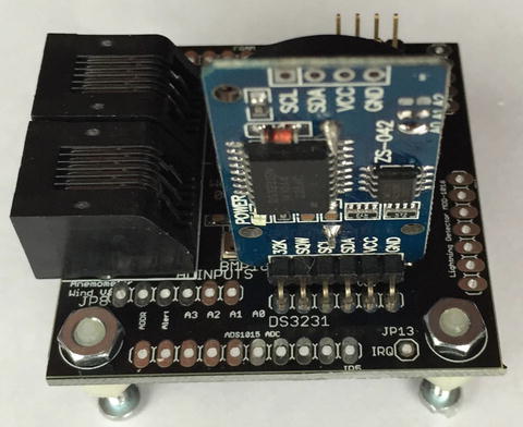
The sensor suite is built on the WeatherPiArduino (shown in Figure 3-7) board but there are several similar boards out there on the market.
Figure 3-7. WeatherPiArduino
The I2C Bus
WeatherPi makes extensive use of the I2C bus on the Raspberry Pi.
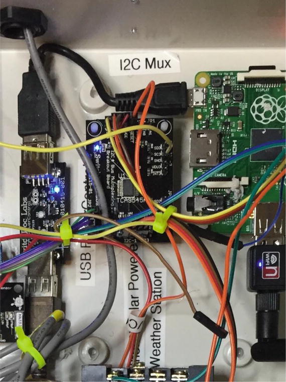
At SwitchDoc Labs, we love data. And we love I2C devices. We like to gather the data using lots of I2C devices on our computers and projects. Project Curacao has a total of twelve, IOTWeatherPi has eleven devices, and SunRover (a solar powered IOT connected robot under development at SwitchDoc) will have over twenty and will require one I2C bus just for controlling the motors. We are always running into conflicts with addressing on the I2C device. Since there are no standards, sometimes multiple devices will have the same address, such as 0x70; and you are just out of luck in running both of them on the same I2C bus without a lot of jimmy rigging. Figure 3-8 shows the I2C Mux wired into the project.
Figure 3-8.I2CMux in IOTWeatherPi
To get around this addressing problem (and our conflict with an INA3221 and the Inside Humidity Sensor) we added an I2C Bus Multiplexer to the design, which allows us to have many more I2C devices on the bus, regardless of addressing conflicts. Table 3-2 provides a list of I2C devices in IOTWeatherPi.
Table 3-2.I2C Addresses in IOTWeatherPi
|
Device |
I2C Address |
|
BMP180 or BMP280 Barometric Pressure |
0x77 |
|
Real Time Clock DS3231 |
0x68 |
|
ATC EEPROM |
0x56 |
|
ADS1015 Analog to Digital Converter |
0x49 |
|
FRAM Non-volatile storage |
0x50 |
|
ADS1015 on SunAirPlus |
0x48 |
|
INA3221 3 Channel Voltage/Current Monitor on SunAirPlus |
0x40 |
|
HTU21D-F Humidity Sensor |
0x40 |
|
Embedded Adventures Lightning Detector |
0x03 |
|
AM2315 Outdoor Temp/Humidity |
0x5C |
|
I2C 4 Channel I2C Bus Mux |
0x73 |
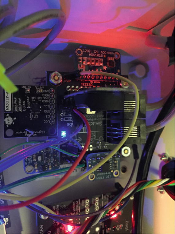
Following is what the I2C bus looks like on the Raspberry Pi. There are four independent buses shown for the I2C bus, but note that IOTWeatherPi only uses Bus 0 and Bus 1. Figure 3-9 shows a fully populated WeatherPiArduino board.
Figure 3-9.WeatherPiArduino Fully Loaded with Sensors
Test SDL_Pi_TCA9545 Version 1.0 - SwitchDoc Labs
Sample uses 0x73
Program Started at:2015-05-10 20:00:56
-----------BUS 0-------------------
tca9545 control register B3-B0 = 0x1
ignore Interrupts if INT3' - INT0' not connected
tca9545 control register Interrupts = 0xc
0 1 2 3 4 5 6 7 8 9 a b c d e f
00: 03 -- -- -- -- -- -- -- -- -- -- -- --
10: -- -- -- -- -- -- -- -- -- -- -- -- -- -- -- --
20: -- -- -- -- -- -- -- -- -- -- -- -- -- -- -- --
30: -- -- -- -- -- -- -- -- -- -- -- -- -- -- -- --
40: 40 -- -- -- -- -- -- -- -- 49 -- -- -- -- -- --
50: 50 -- -- -- -- -- 56 -- -- -- -- -- -- -- -- --
60: -- -- -- -- -- -- -- -- 68 -- -- -- -- -- -- --
70: -- -- -- 73 -- -- -- 77
-----------------------------------
-----------BUS 1-------------------
tca9545 control register B3-B0 = 0x2
ignore Interrupts if INT3' - INT0' not connected
tca9545 control register Interrupts = 0xe
0 1 2 3 4 5 6 7 8 9 a b c d e f
00: -- -- -- -- -- -- -- -- -- -- -- -- --
10: -- -- -- -- -- -- -- -- -- -- -- -- -- -- -- --
20: -- -- -- -- -- -- -- -- -- -- -- -- -- -- -- --
30: -- -- -- -- -- -- -- -- -- -- -- -- -- -- -- --
40: 40 -- -- -- -- -- -- -- 48 -- -- -- -- -- -- --
50: -- -- -- -- -- -- -- -- -- -- -- -- -- -- -- --
60: -- -- -- -- -- -- -- -- -- -- -- -- -- -- -- --
70: -- -- -- 73 -- -- -- --
-----------------------------------
-----------BUS 2-------------------
tca9545 control register B3-B0 = 0x4
ignore Interrupts if INT3' - INT0' not connected
tca9545 control register Interrupts = 0xc
0 1 2 3 4 5 6 7 8 9 a b c d e f
00: -- -- -- -- -- -- -- -- -- -- -- -- --
10: -- -- -- -- -- -- -- -- -- -- -- -- -- -- -- --
20: -- -- -- -- -- -- -- -- -- -- -- -- -- -- -- --
30: -- -- -- -- -- -- -- -- -- -- -- -- -- -- -- --
40: -- -- -- -- -- -- -- -- -- -- -- -- -- -- -- --
50: -- -- -- -- -- -- -- -- -- -- -- -- -- -- -- --
60: -- -- -- -- -- -- -- -- -- -- -- -- -- -- -- --
70: -- -- -- 73 -- -- -- --
-----------------------------------
-----------BUS 3-------------------
tca9545 control register B3-B0 = 0x8
ignore Interrupts if INT3' - INT0' not connected
tca9545 control register Interrupts = 0xc
0 1 2 3 4 5 6 7 8 9 a b c d e f
00: -- -- -- -- -- -- -- -- -- -- -- -- --
10: -- -- -- -- -- -- -- -- -- -- -- -- -- -- -- --
20: -- -- -- -- -- -- -- -- -- -- -- -- -- -- -- --
30: -- -- -- -- -- -- -- -- -- -- -- -- -- -- -- --
40: -- -- -- -- -- -- -- -- -- -- -- -- -- -- -- --
50: -- -- -- -- -- -- -- -- -- -- -- -- -- -- -- --
60: -- -- -- -- -- -- -- -- -- -- -- -- -- -- -- --
70: -- -- -- 73 -- -- -- --
-----------------------------------
Sizing Your Solar Power System
One of the first things that comes up in a solar powered design is how to design the power system. The three main questions to be asked and answered are the following:
|
1. |
|
|
|
2. |
|
|
|
3. |
|
The first thing you need to do when designing a solar powered system is to determine the power requirements for your solar powered design. Our criteria are that we want the IOTWeatherPi Raspberry Pi Model A to run all day and at least three hours before sunrise and three hours after sunset. Our goals and budget influence our hardware choices, so they are not totally independent. Figure 3-10 shows the solar panels with the AM2315 outside temperature sensor on the side of the enclosure.
Figure 3-10.Solar Power Panels on IOTWeatherPi
Table 3-3 contains estimated power consumption for models of the Raspberry Pi, including a Wireless USB dongle. We are assuming in each of these that you turn the HDMI port off, which saves ∼20mA.
Table 3-3.Estimated Power Consumption for Raspberry Pi Models
|
|
Model A |
Model A+ |
Model B |
Model B+ |
Model Pi2 B |
|
Current (mA) |
260(200) |
195(135) |
480(420) |
290(230) |
304(240) |
|
Power (W) |
1.3(1.0) |
0.975 (0.675) |
2.4 (2.1) |
1.45 (1.15) |
1.52 (1.2) |
|
Source |
Measured |
Measured |
Measured |
Measured |
Measured |
All of the above measurements include about 60mA for the USB WiFi Dongle. Parenthetical numbers are without the 60mA.
Based on the above, first I will lay out my assumptions for our Raspberry Pi Model A+-based design. The LiPo batteries chosen will store 6600mAh. Why choose the Model A+? It's the lowest current consuming Raspberry Pi.
What is mAh (milli Amp hours)? A 6600mAh means you can take 100mA for 66 hours, theoretically. In actuality, you will not be able to get more than about 80% on average depending on your battery. How fast you discharge them also makes a big difference. The slower the discharge rate, the more mAh you can get out of the battery. For comparison, an AA battery will hold about 1000mAh[en.wikipedia.org/wiki/AA_battery] and a D battery will hold about 10000mAh[en.wikipedia.org/wiki/AA_battery].
In a system like this, it is best to charge your LiPo batteries completely and then hook up the computer and see how long it takes to discharge the battery and die. We did this test on the IOTWeatherPi system. The results are here on switchdoc.com [ www.switchdoc.com/?p=1926 ].
Given these we can calculate total Raspberry Pi Model A runtime during a typical day:
PiRunTime = (8 Hours * 70% * 1060mA) *85% / (195mA) = 25 hours
Our goal was for 24 hours, so it looks like our system will work. So 16 Hours of running the Raspberry Pi Model A+ on batteries alone will take (195mA/85%)*16 Hours = 3670mAh, which is comfortably less than our 6600mAh batteries can store. The WIFI dongle added about 60mA on average. It was enabled the entire time the Raspberry Pi was on. No effort was made to minimize the power consumed by the WiFi dongle. Your results will depend on what other loads you are driving, such as other USB devices, GPIO loads, I2C devices, etc.
Note that during the day, on average, we are putting into the battery about 6000mAh.
This also means a larger battery than 6600mAh will not make much difference to this system.
So, on a bright sunny day, we should be able to run 24 hours a day. Looking at the results from IOTWeatherPi being out in the sun for a week, this seems to be correct. However, it will be cloudy and rainy and your system will run out of power. The next most-important part of the design is how to handle brownouts! See the section below about how to hand this nasty little problem.
The four most important parts of verifying your Solar Power Design:
Power Up and Power Down
The power system in Weather Pi consists of four parts:
We are using 2 3.4W Solar Panels from Voltaic Systems. These are high-quality panels that we have used in previous projects and last a long time even in the tropical sun. The picture above is of the same panels on Project Curacao after six months in the sun. Those are clouds reflected on the panels, not dirt. The panels are perfect.
We selected a 6600mAh battery from Adafruit for this design. See the "Sizing your Solar System" step below .
We are using a SunAirPlus Solar Power Controller in this design. In Figure 3-11 you can see how the solar power control is placed in the enclosure, above the Raspberry Pi.
Figure 3-11.Solar Power Controller in Lower Part of Box
SunAirPlus includes an I2C INA3221[ www.switchdoc.com/2015/03/sunairplus-solar-power-ina3221-python-raspberry-pi-library-released/ ] 3 Channel Current /Voltage Monitor and a I2C 4 channel 12 bit Analog to Digital Converter (ADS1015). The INA3221 allows you to monitor all of the major currents and voltages in the system (Battery / Solar Panels / Load - Computer ). You can tell what your solar power project is doing in real time.
Following are some results from the SunAirPlus board using the onboard INA3221. You can see that the battery is almost fully charged, and the solar cell voltage (actually a variable power supply on the test bench) is 5.19V and it is supplying 735mA .
Test SDL_Pi_INA3221 Version 1.0 - SwitchDoc Labs
Sample uses 0x40 and SunAirPlus board INA3221
Will work with the INA3221 SwitchDoc Labs Breakout Board
------------------------------
LIPO_Battery Bus Voltage: 4.15 V
LIPO_Battery Shunt Voltage: -9.12 mV
LIPO_Battery Load Voltage: 4.14 V
LIPO_Battery Current 1: 91.20 mA
Solar Cell Bus Voltage 2: 5.19 V
Solar Cell Shunt Voltage 2: -73.52 mV
Solar Cell Load Voltage 2: 5.12 V
Solar Cell Current 2: 735.20 mA
Output Bus Voltage 3: 4.88 V
Output Shunt Voltage 3: 48.68 mV
Output Load Voltage 3: 4.93 V
Output Current 3: 486.80 mA
You can use this board to power your projects and add a servo or stepper motor to allow it to track the sun using photoresistors to generate even more power.
The USB PowerController Board is basically a controlled Solid State Relay to turn the power on and off to the Raspberry Pi. This board sits between the Solar Power Controller (SunAirPlus) and a Raspberry Pi Model A+. The input to the board was designed to come directly from a LiPo battery so the computer won't be turned on until the LiPo battery was charged up above ∼ 3.8V. A hysteresis circuit is provided so the board won't turn on and then turn immediately off because the power supply is yanked down when the computer turns on (immediately putting a load on the battery). This really happens!!!! You kill Raspberry Pi SD Cards this way.
The Brownout Problem
In this important step, we are going to discuss the problem of powering down and up your Raspberry Pi. In Solar Powered systems, this is called the "Brownout Problem ." We will be showing how to use a simple device, the USB Power Control [ www.switchdoc.com/usb-powercontrol-board/ ] , from SwitchDoc Labs to solve this problem.
One of the most important issues in designing a Raspberry Pi Solar Power System is turning on and off. The “Brownout Problem” is a real issue. Why worry? If you have a long string of cloudy days, you may run your battery down. You can compensate for this in your design by adding more panels and more batteries, but that can get really expensive and your system might still run out of power, just a lot less frequently .
Shutting Off the Pi
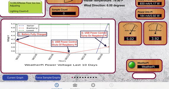
Shutting a Raspberry Pi off is pretty easy. When the battery voltage falls below some value, you just do a “sudo shutdown -h now” and your Raspberry Pi will shut down cleanly. After doing the test talked about here [ www.switchdoc.com/?p=1926 ], we chose 3.5V as the voltage to shut down the Raspberry Pi. Figure 3-12 shows the graph of the data after implementing these values.
Figure 3-12.Testing the Behavior of the IOTWeatherPi Power System
Note that in most solar power systems, you need to monitor the battery voltage and not the 5V power supply because with most modern voltage booster systems, the circuitry will work very hard to keep the 5V going and then just give up crashing to a much lower voltage when it runs out of power.
That means your computer would have little or no warning when the voltage is about to drop. By monitoring the battery voltage, you can tell when the battery is getting low enough and then shut down your computer safely. For LiPo batteries, this will be when your voltage gets down to about 3.5V or so. This can all be monitored with the SunAirPlus solar charge controller that we are using in IOTWeatherPi.
Starting the Pi
Enough about shutting down the computer. What about starting it up?
The Issue
You can’t just let the controller power up the computer. The problem is that the supply voltage will move up and down until there is enough charge in the battery to fully supply the computer. When the computer turns on (connecting a full load), you will pull the battery down hard enough to brown out the computer causing the Raspberry Pi to crash. This constant rebooting cycle can corrupt and ruin your SD card and cause your computer to never boot at all, even when the power is restored. We had this VERY thing happen to us 3500 miles away with Project Curacao[ www.switchdoc.com/2015/02/solar-power-project-curacao-update/ ]. Arduinos are more tolerant of this, but Raspberry Pi’s do not like an ill-behaved power supply. You just can’t be sure of what state the computer will power up at without a good power supply.
This issue can be handled in a number of ways. The first is to use another computer (like an Arduino made to be very reliable by using a WatchDog - see the Reliable Computer series on switchdoc.com [ www.switchdoc.com/2014/11/reliable-projects-watchdog-timers-raspberry-pi-arduinos/ )]to disconnect the Raspberry Pi’s power through a latching relay or MOSFET when there isn’t enough power. Project Curacao ( www.switchdoc.com/project-curacao-introduction-part-1/ ) used this approach.
We didn’t want to add an additional computer to IOTWeatherPi, so we chose a second solution.
Power Your Pi Up and Down with the USB Power Control
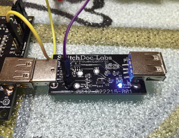
A second (and cheaper!) way of handling the brownout and power-up problem is to use a dedicated power controller that will shut the power off to the Raspberry Pi and restore the power when the battery voltage is high enough to avoid ratcheting the supply voltage up and down because of the load of the Raspberry Pi. This is called Hysteresis. We have designed a board to do just this (called the USB PowerController[ www.switchdoc.com/usb-powercontrol-board/ ]) that will plug between the USB coming out of the SunAir Solar Power Controller and the Raspberry Pi as in Figure 3-13.
Figure 3-13.USB PowerControl
The USB Power Controller Board
The USB PowerControl board is a USB to USB solid state relay.

