Users Online
· Members Online: 0
· Total Members: 188
· Newest Member: meenachowdary055
Forum Threads
Latest Articles
Articles Hierarchy
#02_13 Arduino Security Camera with Motion Detection
Arduino Security Camera with Motion Detection
Security is a concern for everyone. If you want to capture and record any activity within your home or office for security purposes, thousands of security camera models are available to fulfill the task. You can, however, make your own security camera, complete with Internet feedback and motion detection, and you can also access the camera images from your mobile's browser from anywhere in the world.
In this chapter, you will learn the following:
-
How to use TTL (Through The Lens) Serial Camera directly with NTSC video screen. You can read more about TTL at https://en.wikipedia.org/wiki/Through-the-lens_metering.
-
How to connect TTL Serial Camera to Arduino and Ethernet Shield.
-
How to capture images with TTL Serial Camera.
-
How to create Flickr and Temboo accounts and configure with Arduino Ethernet Shield.
-
How to upload images to the Flickr using the Temboo cloud service.
-
How to capture images with built-in motion sensor and upload them to the Flickr.
Prerequisites
The following materials will be needed to get started with the chapter:
-
Arduino UNO Rev3 board (https://store.arduino.cc/product/A000066).
-
Arduino Ethernet Shield Rev3 (https://store.arduino.cc/product/A000072).
-
Arduino Ethernet board (optional)— if you use an Arduino Ethernet board, you do not need an Arduino UNO board. Arduino Ethernet board is a compact collection of an Arduino board and Ethernet Shield. (https://www.sparkfun.com/products/11229).
-
Micro SD Card—Use 4GB Class 4 SDHC. (https://www.adafruit.com/products/102).
-
TTL Serial Camera (http://www.adafruit.com/products/397).
-
9V DC power supply (https://www.sparkfun.com/products/10273).
-
USB A-to-B cable (https://www.sparkfun.com/products/512).
-
RCA jack (https://www.sparkfun.com/products/8631).
-
Ethernet Cable (https://www.sparkfun.com/products/8915).
-
Optional - NTSC/PAL TFT display – 4.3" Diagonal (http://www.adafruit.com/product/946).
-
Jumper wires.
-
Wire Strippers (https://www.sparkfun.com/products/12630).
-
Soldering iron (EU:230V AC: https://www.sparkfun.com/products/11650, US 110V AC: https://www.sparkfun.com/products/9507).
Getting started with TTL Serial Camera
The heart of the TTL Serial Camera module (the product page at Adafruit named it as TTL Serial JPEG Camera) is the VIMICRO VC0706 Digital video Processor. The following are some of the features that a VC0706 digital video processor has:
-
CMOS sensor interface and digital video input interface, so it can capture video using the CMOS sensor or external TV decoder
-
Embedded TV encoder and video DAC, so it can directly output NTSC/PAL video streams to TV monitors and other 75 ohm display devices
-
Preimage processing and M-JPEG compression ability
-
NTSC video output resolution up to 712 x 486
-
PAL video output resolution up to 704 x 576
-
Maximum frame rate; 60fps @ 27MHz in NTSC and 50fps @ 27MHz in PAL
-
Ability to change the brightness, saturation, and hue of images
-
Auto brightness and auto contrast adjustment
-
Motion detection
The VC0706 chipset specification mentioned that it supports both NTSC and PAL but the TTL Serial Camera module only implemented NTSC.
The TTL Serial Camera is only just a breakout board and has no wires, so you need to solder wires into the connection pads. It has five connection pads, which are 2mm apart from each other.

A Fritzing representation of TTL Serial Camera—top view
The pin labels and their core operation is listed as follows:
-
CVBS: Outputs NTSC monochrome video stream
-
GND: This is the NTSC video ground, located next to the CVBS pad
-
TX: Data transmits from the module
-
RX: Data reception to the module
-
GND: Negative
-
+5V: Positive
Wiring the TTL Serial Camera for image capturing
You need four wires if you are only planning to capture color images with a TTL serial camera.

Wiring for image capturing in the JPEG format
Solder wires to the connection pads are mentioned as:
-
Solder wire 1 (red) into the +5v connector pad
-
Solder wire 2 (black) into the GND connector pad
-
Solder wire 3 (white) into the TX connector pad
-
Solder wire 4 (green) into the RX connector pad
Wiring the TTL Serial Camera for video capturing
The TTL Serial Camera board only supports NTSC video output and cannot be used as PAL. Now, solder two additional wires as shown in the following diagram:

Wiring for video capturing with NTSC monochrome
Solder additional wires to the connection pads are mentioned as:
-
Solder wire 5 (black) into the GND connector pad
-
Solder wire 6 (yellow) into the CVBS connector pad
Testing NTSC video stream with video screen
Use an RCA jack and solder two wires, as stated here:
-
Solder a yellow wire to the center terminal
-
Solder a black wire to the outer terminal
Then make the other connections as follows:

-
Connect the yellow wire to the RCA jack's signal terminal.
-
Connect the black wire to the RCA jack's ground terminal.
-
Now, connect the TTL serial camera to a regulated 5V power source, the red wire to positive, and the black wire to negative. You can use an Arduino board to get the regulated 5V power. Connect the red wire to Arduino 5V pin and the black wire to Arduino GND pin, and connect Arduino to the 9v power supply.
-
Finally, connect the soldered RCA jack to the NTSC monitor using an RCA video cable. If you are living in a region that does not support the NTSC broadcasting system, then you have to purchase a basic NTSC/PAL monitor. But some televisions support both NTSC and PAL broadcasting systems. Check your television's user manual for more information. If it does not support NTSC, then you have to purchase an NTSC- supported monitor from Adafruit (http://www.adafruit.com/product/946), or search eBay for a cheaper one.
Now, power up the monitor. You can see the monochrome video that has been captured by the TTL Serial Camera module. Next, we will move on to the most difficult part.
Connecting the TTL Serial Camera with Arduino and Ethernet Shield
Stack up your Arduino Ethernet Shield with the Arduino board as you did in the previous chapters and perform the following steps:
-
Connect your TTL Serial Camera module with the Arduino and Ethernet Shield as shown in the diagram below. Here, we will use two Arduino digital pins and a Software Serial port to communicate with the camera.

The Adafruit VC0706 Serial JPEG Camera is connected with Arduino Ethernet Shield
-
Connect camera TX to Arduino digital pin 2 and camera RX to Arduino digital pin 3.
-
Connect camera GND to Arduino GND and camera 5V to Arduino 5V.
-
Now insert a Micro SD card into the SD card connector on the Ethernet shield. Remember the Arduino communicates with the SD card using digital pin 4.
-
Download the Adafruit VC0706 camera library from GitHub by navigating to https://github.com/adafruit/Adafruit-VC0706-Serial-Camera-Library. After it has been downloaded, extract the ZIP file into your local drive.
-
Next, rename the folder Adafruit-VC0706-Serial-Camera-Library to Adafruit_VC0706, and move the renamed Adafruit_VC0706 folder to the libraries folder. Note that the libraries folder resides in the Arduino IDE folder.
Alternatively, in the recent version of Arduino IDE, you can add a new library ZIP file by navigating to Sketch | Include Library | Add .ZIP Library…. Then, browse the ZIP file and click on the Open button. This will add the particular library to the Arduino libraries folder.
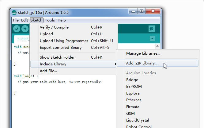
Including a new library by a ZIP file
-
Finally, restart the Arduino IDE.
The Adafruit VC0706 camera library includes sample sketches for image capturing and motion detection. You can verify them by navigating to File | Examples | Adafruit VC0706 Serial Camera Library.
Image capturing with Arduino
You can capture and save images in a Micro SD card using the Adafruit VC0706 camera library. Use the following steps to play with the sample sketches that ship with the Adafruit VC0706 camera library:
-
Open the Arduino IDE and go to File | Example | Adafruit_VC0706 | Snapshot.
-
Upload the code on your Arduino board. (Also, you can copy the code B04844_04_01.ino from the Chapter 4 code folder)
-
Once uploaded, the camera will capture and save an image in the SD card with a resolution of 640 x 480. On the Arduino serial monitor, you can see some useful information about the image that is taken, such as the image resolution, image size in bytes, and the number of seconds taken to capture and save the image, which is in the JPG format.
Press the Arduino RESET button to capture the next image. You can use the RESET button to capture any subsequent images. But this sketch is limited to capturing images up to 100 times.
Insert your Micro SD card into the card reader of your PC, browse the SD card, and open the images using any image viewer installed in your computer. Cool!
Now, we will look into some important points of this sample code in the next section so that we can modify the code according to our requirements.
The Software Serial library
Arduino comes with hardware serial enabled, where pins 0 and 1 can be used to communicate with the serial devices. Pin 0 transmits (TX) the data to out and pin 1 receives (RX) data to in. However, using the Software Serial library, you can convert any digital pin in to TX or RX. For this project, we will use digital pins 2 for RX and 3 for TX.
SoftwareSerial(RX, TX)
The following code snippet shows how to use the Software Serial library to convert Arduino digital pin 2 as RX and digital pin 3 as TX:
// On Uno: camera TX connected to pin 2, camera RX to pin 3:
SoftwareSerial cameraconnection = SoftwareSerial(2, 3);
How the image capture works
The following code snippets show the important sections of the Arduino sketch.
To create a new object using the Adafruit_VC0706 class, write a code line similar to the following. This will create the object cam:
Adafruit_VC0706 cam = Adafruit_VC0706(&cameraconnection);
The camera module can be used to take images in three different sizes. The largest size of the image we can take is 640 x 480. In the following code snippet, the camera will capture images in resolutions of 640 x 480. Uncomment the line you want to set as the image size.
// Set the picture size - you can choose one of 640x480, 320x240 or 160x120
// Remember that bigger pictures take longer to transmit!
cam.setImageSize(VC0706_640x480); // biggest
//cam.setImageSize(VC0706_320x240); // medium
//cam.setImageSize(VC0706_160x120); // small
The takePicture() function of the cam object can be used to take a picture from the camera.
if (! cam.takePicture())
Serial.println("Failed to snap!");
else
Serial.println("Picture taken!");
...
Then, create a filename for the new file by looking at the existing files stored in the SD card.
Finally, write the new image file on the SD card. This process is quite complicated and time consuming.
Uploading images to Flickr
Rather than saving the captured image in an SD card, we can automatically upload the image to Flickr. In the next section, we will learn how to do this with Flickr and Temboo cloud service.
Creating a Flickr account
Follow these steps to create a Flickr account:
-
Open your Internet browser, navigate to https://www.flickr.com/.
-
Click on the Sign In link in the top-right corner of the page. If you already have a Yahoo account, you can use the same login credentials to log in to Flickr.
-
If you don't have a Yahoo account, click on Sign Up in the top-left corner of the page, or on the Sign up with Yahoo button in the center of the page and follow the instructions to create a new Yahoo account.
-
After you have successfully logged in to Flickr, click on the Explore menu in the top, and in the resulting drop-down menu, click on App Garden.
-
The App Garden page will appear, as shown in the following screenshot:
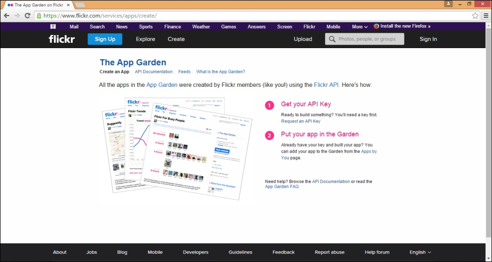
Flickr: The App Garden page
-
Click on the Create an App link if it is not selected by default.
-
Under Get your API Key, click on Request an API Key, as shown in the following screenshot:
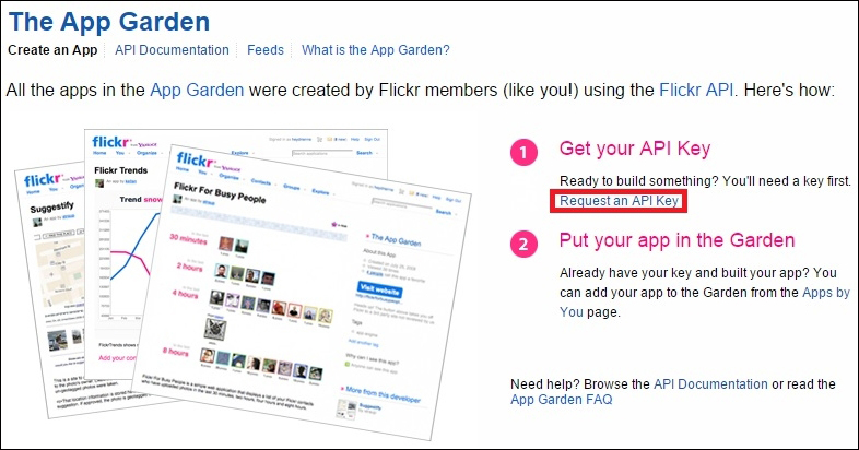
Flickr: The App Garden page
-
Click on the APPLY FOR A NON-COMMERCIAL KEY button, as shown here:

Flickr: The App Garden page
-
The Tell us about your app page will appear, as shown in the following screenshot:
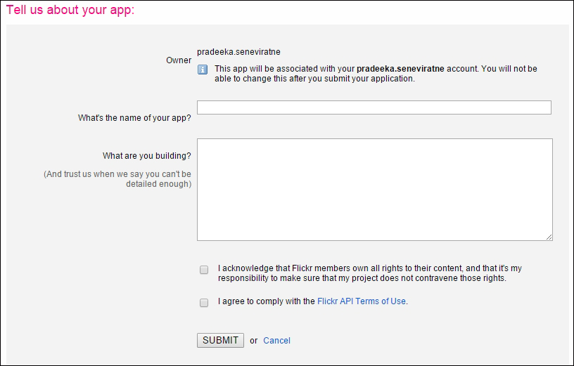
Flickr: The App Garden page
-
Fill the following text boxes:
-
-
What's the name of your app?: Give a short name for your app
-
What are you building?: Give a brief description about your app and its purpose
-
-
-
Check the two checkboxes.
-
Click on the SUBMIT button.
-
The API Key and Secret for your new app will be displayed in the next page, as shown here:
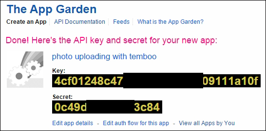
Flickr: The App Garden page
Copy and paste the API Key and Secret into a notepad, if you think it will be easy for your reference later.
That's it for the moment. Later, you have to again visit the Flickr website, so don't sign out from Flickr. To access Flickr services, we have to create a Temboo account and make some configurations.
Creating a Temboo account
Temboo provides normalized access to 100+ APIs and databases. It provides code-based, task-specific code components called Choreos that can be used with the Arduino language to simplify the complex tasks such as uploading images to Flickr, sending SMS, sending Twitter tweets, and many more.
Let's look at how to create a new Temboo account, so you can use this account for experimenting with Temboo and Arduino.
-
First, navigate to https://temboo.com/ using your Internet browser.
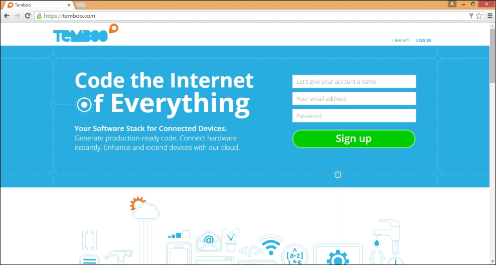
The Temboo home page
-
Then, you have to create a new user account in Temboo.
-
In the top-right corner of the page, there is a section for Sign up. Enter a name for your account, a valid e-mail address, and a password (which must have eight characters, at least one letter, and one number); agree with Temboo terms and click on the Sign up button. The Welcome page will appear, as shown here:
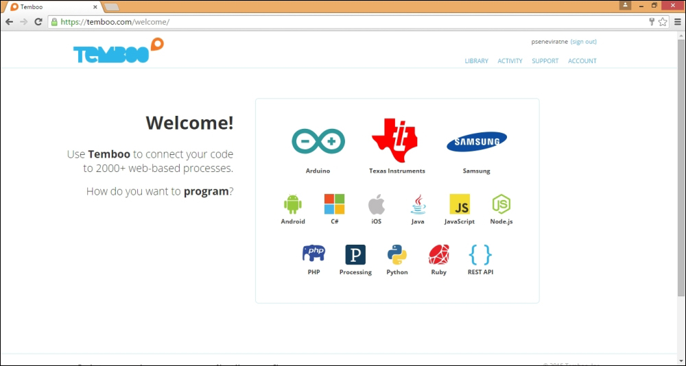
The Temboo Welcome page
Creating your first Choreo
Now, we are ready to create our first Choreo. To do this, we need to complete a series of configurations and processing steps with Temboo.
Initializing OAuth
In the top-right of the Temboo web page, click on LIBRARY. The LIBRARY page will appear. Under the CHOREOS pane (listed in the left-hand side of the page) go to Flickr | OAuth by clicking on the down arrow signs, and finally, click on InitializeOAuth.
First, enable IoT Mode, as shown in the following screenshot:
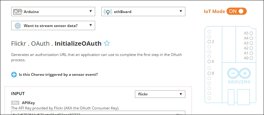
Enabling IoT mode
Then, configure the form as shown in the following steps:
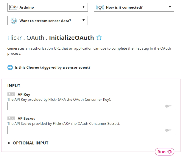
Initialize OAuth for Flicker
-
Select Arduino from the left drop-down menu. The default is Arduino Yún.
-
Select Arduino Ethernet from the How is it connected? drop-down menu. The Tell us about your shield dialog box will appear.
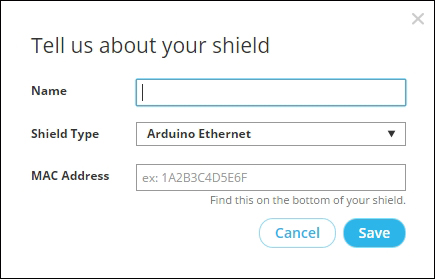
Tell us about your shield dialog box
-
Type a name for your shield and type the MAC address of your shield in the MAC Address field without any spaces. Then, click on the Save button.
-
Under the INPUT section, enter the following:
-
-
APIKey: Enter the API key provided by Flickr
-
APISecret: Enter the API Secret provided by Flickr
-
-

-
Click on the Run button to process the OAuth initialization. In a few seconds, the process will generate following output:
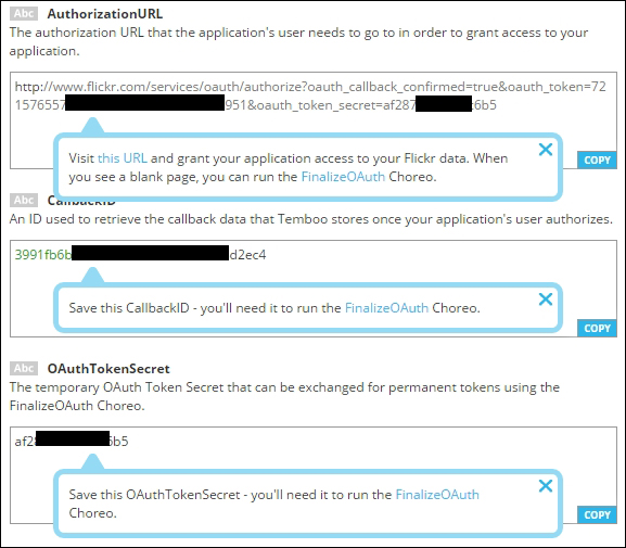
Output after the process of OAuth initialization for Flickr
The following listing of information is extracted from the preceding output. The information will differ according to your setup.
-
-
-
Authorization URL: http://www.flickr.com/services/oauth/authorize?oauth_callback_confirmed=true&oauth_token=7215xxxxxxxxxxxxxxxxxxxxx951&oauth_token_secret=af287xxxxxxxc6b5
-
CallbackID: 3991fb6b-xxxxxxxxxxxxxxx-b83e453d2ec4
-
OAuthTokenSecret: af287xxxxxxxc6b5
-
-
-
Open a new browser tab and paste the authorization URL into the address bar and press the Enter key on your key board. A page will appear for authorization confirmation, as shown here:
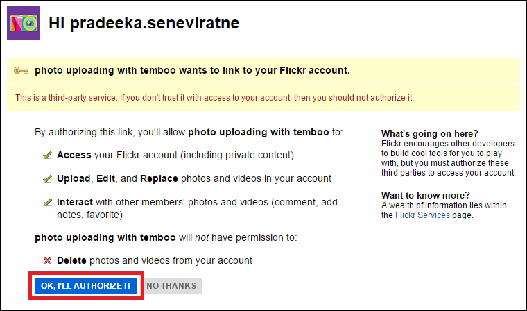
A Flicker user account authorization page
-
Click on the OK, I'LL AUTHORIZE IT button. Now, you will be navigated to a blank web page.
Finally, you have successfully authorized your app.
Finalizing OAuth
Perform the following steps to finalize OAuth:
-
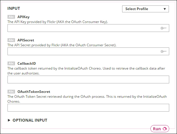
Click on FinalizeOAuth after navigating to Flickr | OAuth. The FinalizeOAuth page will appear, as shown in the following screenshot:
FinalizeOAuth for Flickr
-
Fill the following text boxes with the relevant information:
-
-
APIKey: The API Key provided by Flicker for your app
-
APISecret: The API secret provided by Flickr for your app
-
CallbackID: The callback token returned by the InitializeOAuth process
-
OAuthTokenSecret: The OAuth Token Secret retrieved during the OAuth process
-
-
-
Click on the Run button to process. Now you have finalized the OAuth process for your Flickr app.
Generating the photo upload sketch
In this section, you will learn how to generate the photo upload sketch. To achieve this, you need to perform the following steps:
-
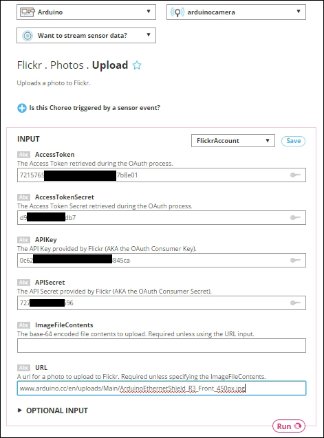
Under CHOREOS go to Flickr | Photos and then click on Upload. The following screen will appear:
A Flicker photo upload Choreo
-
Fill the textboxes with the following information:
-
-
AccessToken: The Access Token retrieved during the OAuth process.
-
AccessTokenSecret: The AccessTokenSecret retrieved during the OAuth process.
-
APIKey: The API Key provided by Flickr.
-
APISecret: The API Secret provided by Flickr.
-
ImageFileContents: Keep this field blank.
-
URL: Any valid image URL. (for example, use https://www.arduino.cc/en/uploads/Main/ArduinoEthernetFront450px.jpg). Note that this specified image will be uploaded to your Flickr account for testing.
-
-
-
Click on the Run button to process the image upload to Flickr. If everything is correct, you will get a response, as shown in the following screenshot:

-
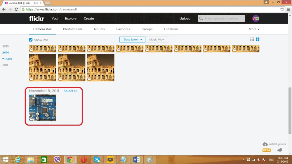
To verify the uploaded image, sign in to your Flickr account. On the Flickr web page, click go to You | Camera Roll. You can see the uploaded image by the Temboo cloud service, as shown here:
-
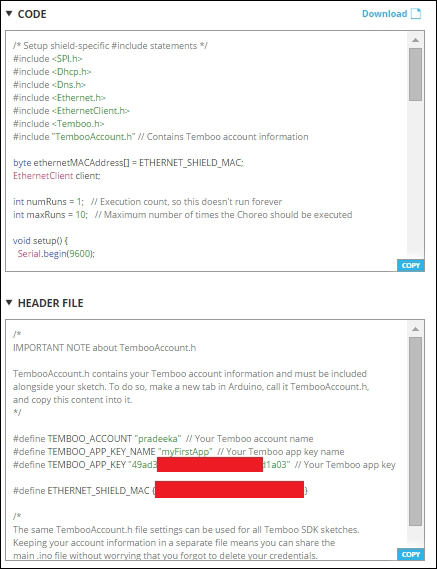
Continue with step 3, and scroll down the page. You can see two sections, CODE and HEADER FILE:
-
Now open a new Arduino IDE and copy and paste the generated code inside the CODE box.
-
Create a folder and rename it to TembooAccount inside your Arduino installation directory, and then under the Libraries folder. Copy the code inside the HEADER FILE box and paste it to a new Notepad file. Save the file as TembooAccount.h inside the TembooAccountfolder.
-
Then, verify the code and upload it into your Arduino board.
-
Open the Arduino Serial Monitor. You can see the image upload status and it will upload your same image 10 times on Flickr. Open your Flickr's camera roll and verify the uploaded images.
-
The following Arduino sketch will upload an image (https://www.arduino.cc/en/uploads/Main/ArduinoEthernetFront450px.jpg) maximum of 10 times on Flickr. The sample sketch for this named B04844_04_02.ino can be copied from the Chapter 4 code folder. Also, modify the API key values according to your Flickr and Temboo accounts.
The Arduino sketch for the B04844_04_02.ino file is:
/* Setup shield-specific #include statements */
#include <SPI.h>
#include <Dhcp.h>
#include <Dns.h>
#include <Ethernet.h>
#include <EthernetClient.h>
#include <Temboo.h>
#include "TembooAccount.h" // Contains Temboo account information
byte ethernetMACAddress[] = ETHERNET_SHIELD_MAC;
EthernetClient client;
int numRuns = 1; // Execution count, so this doesn't run forever
int maxRuns = 10; // Maximum number of times the Choreo should be executed
void setup() {
Serial.begin(9600);
// For debugging, wait until the serial console is connected
delay(4000);
while(!Serial);
Serial.print("DHCP:");
if (Ethernet.begin(ethernetMACAddress) == 0) {
Serial.println("FAIL");
while(true);
}
Serial.println("OK");
delay(5000);
Serial.println("Setup complete.\n");
}
void loop() {
if (numRuns <= maxRuns) {
Serial.println("Running Upload - Run #" + String(numRuns++));
TembooChoreo UploadChoreo(client);
// Invoke the Temboo client
UploadChoreo.begin();
// Set Temboo account credentials
UploadChoreo.setAccountName(TEMBOO_ACCOUNT);
UploadChoreo.setAppKeyName(TEMBOO_APP_KEY_NAME);
UploadChoreo.setAppKey(TEMBOO_APP_KEY);
// Set Choreo inputs
String APIKeyValue = "0c62beaaxxxxxxxxxxxxxxxe3845ca";
UploadChoreo.addInput("APIKey", APIKeyValue);
String AccessTokenValue = "7215xxxxxxxxxxxxxxxxxxxxxx7b8e01";
UploadChoreo.addInput("AccessToken", AccessTokenValue);
String AccessTokenSecretValue = "d95exxxxxxxfddb7";
UploadChoreo.addInput("AccessTokenSecret", AccessTokenSecretValue);
String APISecretValue = "7277dxxxxxxxx7d696";
UploadChoreo.addInput("APISecret", APISecretValue);
String URLValue = "https://www.arduino.cc/en/uploads/Main/ArduinoEthernetFront450px.jpg";
UploadChoreo.addInput("URL", URLValue);
// Identify the Choreo to run
UploadChoreo.setChoreo("/Library/Flickr/Photos/Upload");
// Run the Choreo; when results are available, print them to serial
UploadChoreo.run();
while(UploadChoreo.available()) {
char c = UploadChoreo.read();
Serial.print(c);
}
UploadChoreo.close();
}
Serial.println("\nWaiting...\n");
delay(30000); // wait 30 seconds between Upload calls
}
Connecting the camera output with Temboo
In the previous step, we successfully uploaded an image, which is in a remote server, on Flickr. Now, we are going to upload an image on Flickr, which is captured by the camera.
To do this, first we need to convert the image binary data stream to the base 64 stream.
Download the base64.h library from https://github.com/adamvr/arduino-base64 and extract it inside to the Libraries folder.
Copy and paste the B04844_04_03.ino code from the sketches folder of this chapter and upload it on your Arduino board.
For every 30 seconds, your camera will capture an image and upload on Flickr.
Motion detection
Adafruit TTL serial camera has built-in motion detection capability. Using the VC0706 library, we can capture and upload the detected image to the Flickr. Here, we have used more similar code implementation as explained in the previous section of Motion Detection.
-
Open a new Arduino IDE and copy and paste the code B04844_04_04.ino from the Chapter 4 code folder. Verify and upload the code on your Arduino board.
-
To test the motion, move an object in front of the camera. Wait nearly 30 seconds.
-
To verify the captured image, sign in to your Flickr account, and then, on the Flickr web page, go to You | Camera Roll. You can see the newly uploaded image by the Temboo cloud service.
Let's look at some important points in motion detection that are related to the Arduino sketch.
To enable the motion detection functionality on the VC0706 Camera module, you can use the following code line and set the parameter to true. The default is false. Note that the cam is the object of the VC0706 class.
cam.setMotionDetect(true);
The motion is detected by the following function and it will return true when the motion is detected by the camera module.
cam.motionDetected();
Summary
Throughout this chapter, you learned how to build an Arduino security camera from scratch. Later, you can buy a dummy CCTV camera housing and secure your newly-built camera (Arduino and VC0706 Camera Module) by attaching it inside the housing. It will protect the electronic components from weather and any physical damages.
Further, you can modify the project with an Arduino WiFi shield or Cellular shield to make it wireless. Add a solar panel with a charger if you want to use it in a rural area that doesn't have electricity.
If you want more creativity, you can make a portable handheld camera for image capturing. Remember, you can use the Arduino RESET button to click!
In the next chapter, you will learn how to connect your Arduino to NearBus cloud using NearBus cloud connector, logging solar panel voltage data to the cloud, and displaying live data on the web browser.

