Robot development is one of the big challenges in science and technology. It involves multidisciplinary fields of science and technology. In this chapter, we'll learn and explore how to build an autonomous robot for firefighting, starting with exploring robot platforms and then extending robot capabilities to address firefighting.
We'll learn the following topics:
Introducing autonomous firefighter robots
Exploring robot platforms
Detecting a fire source
Basic remote robot navigation
Detecting obstacles
Designing an autonomous robot
Building an autonomous firefighter robot
Let's explore!
An autonomous robot is one that has its own decision-making capacity to perform tasks such as moving, stopping, pressing a button, or some other specific purpose. Autonomous robots consist of artificial intelligence programs to perform decision computing. Researchers are interested in building a new model for autonomous robots. The more general we make an autonomous robot model, the more attention and effort goes in its development. However, autonomous robot development still needs a specific purpose so it can execute its goals.
An autonomous firefighter robot is one autonomous robot model with the specific purpose of finding and putting out fires. In this chapter, we'll learn and explore how to build an autonomous robot for firefighting.
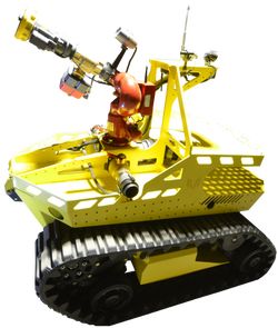
A sample firefighter robot implementation is Thermite 3.0. This robot has a water sprinkler to extinguish fires. You can explore this robot on the official website, http://www.firefightrobot.com. This is what it looks like:

In this section, we'll explore various existing robot platforms that can be applied to build autonomous robots. We will review robot platforms with Arduino and Raspberry capabilities as the robot computing core.
Pololu are an electronics manufacturer and online retailer. They provide various robot platforms. You can see a list of robot platforms at https://www.pololu.com/category/2/robot-kits. Some robot platforms are available as robot kits without soldering. This means you can get your robot up and running without performing soldering on the kit. You can see a list of solder-less robot kits at https://www.pololu.com/category/4/robot-kits-without-soldering.
One robot kit you can make without soldering is the Zumo robot for Arduino. This kit enables your Arduino-based Arduino UNO model to be attached to the board. If you are interested in this robot kit, you can check it out on https://www.pololu.com/product/2510. The Zumo robot for Arduino can be seen here:

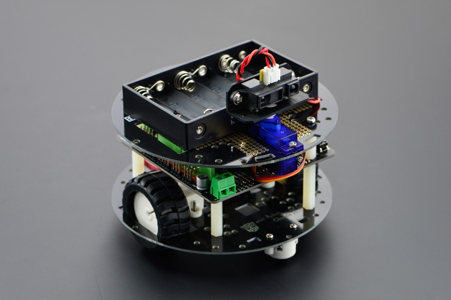
The MiniQ Discovery Arduino robot kit is a robotic platform that is ready to use. This kit is manufactured by DFRobot. They have made custom a Arduino board, called the Romeo board, to manage the robot. This board has a built-in motor driver to manage motor movement.
If you are interested in this kit, you can visit https://www.dfrobot.com/product-1144.html. You can see the MiniQ Discovery Arduino robot kit the following image. In this book, I will use this robot kit for my implementation.
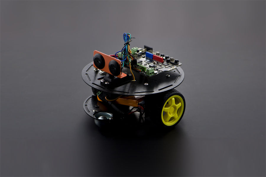
Another robot kit from DFRobot is Turtle kit. This robot uses the Romeo BLE board, which consists of an Arduino UNO model with a BLE module. The Romeo BLE board can be controlled from a smartphone through a BLE network.
You can see the Turtle kit in the following figure. Its website is https://www.dfrobot.com/product-1225.html.
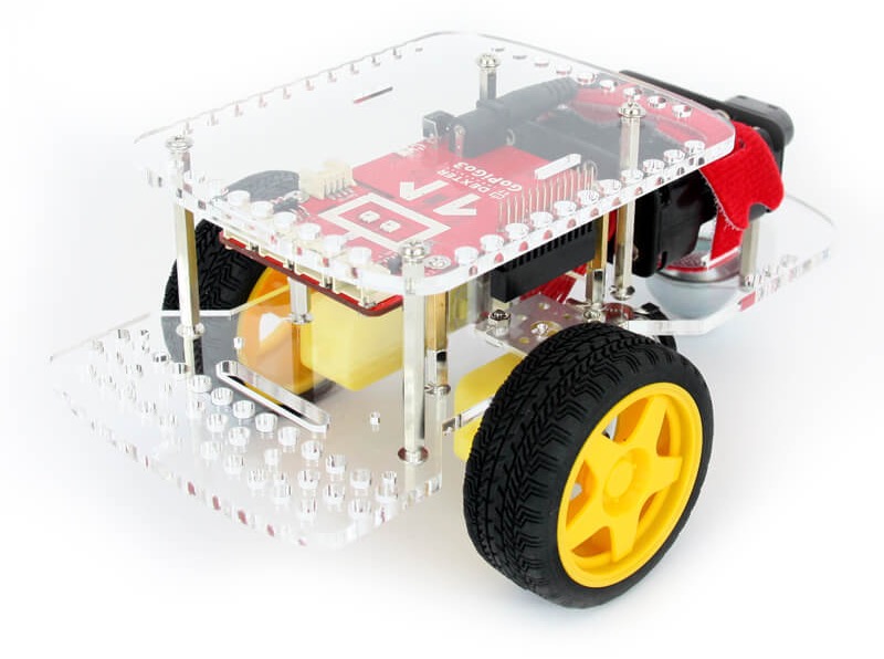
GoPiGo is a robot platform-based Raspberry Pi that is manufactured by Dexter industries. They provide a basic kit that you can bring your own Raspberry Pi to. It's called the GoPiGo robot Base Kit: https://www.dexterindustries.com/shop/gopigo3-robot-base-kit/. You can see its form here:
One of requirements of building an autonomous firefighter robot is to find a fire's source. Fire-detection sensors are available for Arduino and Raspberry Pi. In this section, we'll explore fire-detection sensors.
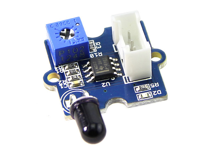
If you have a Grove shield from SeeedStudio, we can use the Grove flame sensor to detect a fire. Technically, this sensor uses the YG1006 sensor with high photosensitivity. This sensor is easy to use on Arduino and Raspberry Pi. If you are interested, you can visit the website to obtain further information: https://www.seeedstudio.com/Grove-Flame-Sensor-p-1450.html. You can see the Grove flame sensor here:
If you don't have a Grove shield for a flame sensor, you can use any flame sensor module, for instance, the flame sensor module from SainSmart. This sensor module enables the Arduino and Raspberry Pi to be attached to the board. This sensor module is cheap, and you can find it at https://www.sainsmart.com/ir-infrared-flame-detection-sensor-module-detect-fire-flame-sensor-for-arduino.html. This is how it looks:
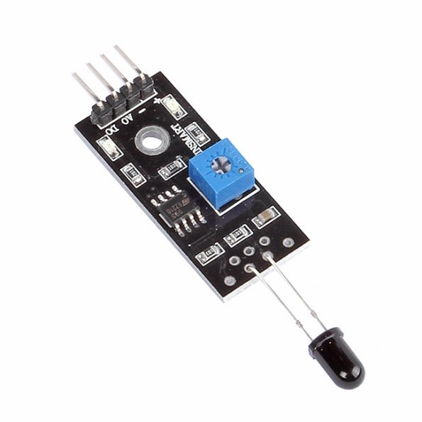
Basically, a flame sensor is cheap and you can find it on Aliexpress, Banggood, or another online store. A flame sensor usually has three or four pins: GND, VCC, A0, and D0. Some flame sensors have the A0 pin or D0 pin or both.
In this section, we'll develop a simple application to detect fire. In this case, we need two modules: flame sensor and buzzer. We will implement this demo using an Arduino board.
Our scenario is to read a fire-detection value from the flame sensor. If the sensor reading reaches a certain value, Arduino will turn on a buzzer device to generate a sound.
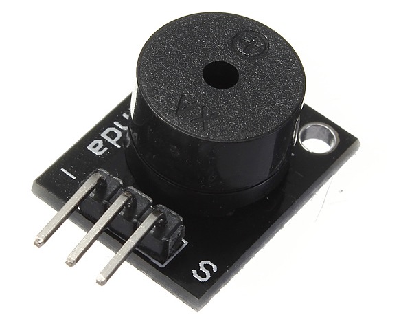
In general, the buzzer device has three pins: GND, VCC and Signal. We can connect the buzzer device to PWM pins on the Arduino. You can see the buzzer device here:
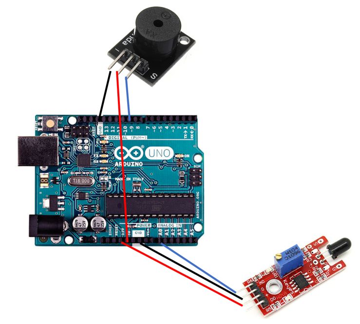
Let's start to implement the hardware wiring. Use the following connections:
Buzzer GND pin connected to Arduino GND pin
Buzzer VCC pin connected to Arduino 5V pin
Buzzer S (signal) pin connected to Arduino digital 9 pin
Flame sensor GND pin connected to Arduino GND pin
Flame sensor VCC pin connected to Arduino 3.3V pin
Flame sensor A0 pin connected to Arduino analog A0 pin
You can see the wiring diagram here:
For example, you can see my wiring implementation on the Arduino Leonardo here:
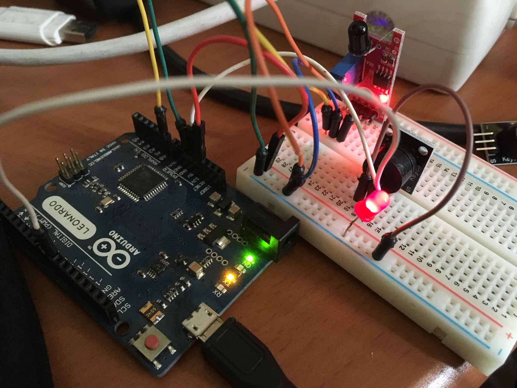
To access the buzzer device and generate sound, we can use the Tone object. You can learn more about it from https://www.arduino.cc/en/Reference/Tone.
The algorithm implementation is easy. Firstly, we open the Arduino software and write the following sketch program:
int flameSensor = A0;
int buzzer = 9;
int val = 0;
void setup() {
pinMode(buzzer,OUTPUT);
Serial.begin(9600);
}
void loop() {
val = analogRead(flameSensor);
if(val > 50) {
Serial.print("Sensor Value = ");
Serial.print(val);
Serial.println(". Fire detected!!");
tone(buzzer,1000);
}
else
noTone(buzzer);
delay(500);
}
Save this sketch as ArduinoFireDetection.
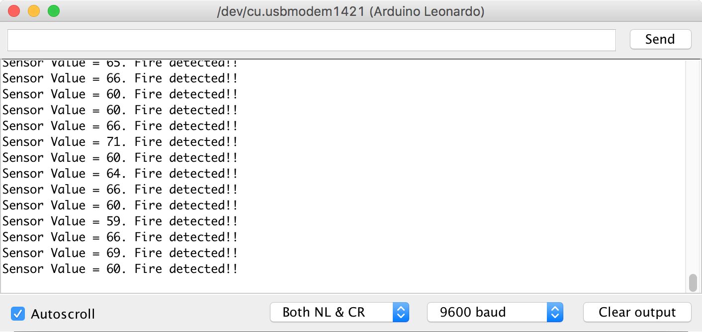
Now you build and upload your sketch program to your Arduino board. After it's uploaded, you can open the Serial Monitor tool from Arduino to see the program output.
Try to move your sensor next to a flame so you can see the sensor value on the Serial Monitor tool. You can see a sample program output here:
How it works
This program initializes all required pins in the setup() function.
int flameSensor = A0;
int buzzer = 9;
int val = 0;
void setup() {
pinMode(buzzer,OUTPUT);
Serial.begin(9600);
}
In loop() function, we read the flame sensor value by calling the analogRead() function. In this case, we set the threshold value to 50. If the reading is greater than 50, we turn on our buzzer device by calling the tone() function:
void loop() {
val = analogRead(flameSensor);
if(val > 50) {
Serial.print("Sensor Value = ");
Serial.print(val);
Serial.println(". Fire detected!!");
tone(buzzer,1000);
}
else
noTone(buzzer);
delay(500);
}
You can change the threshold value based on the results of your experiment.
A robot can be controlled remotely through radio communication. We can use an RF module, Wi-Fi, or Bluetooth to communicate between robot and another system.
In this section, we'll try to control a robot from a computer using Bluetooth. In general, a communication model between a robot and a computer can be described as follows:
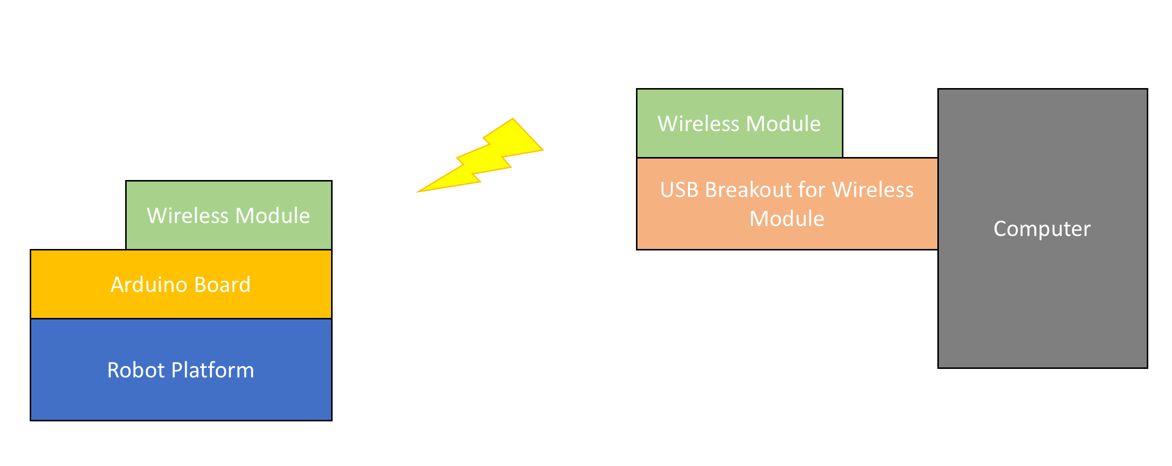
There are some radio and wireless modules that you can use to integrate with your robot to communicate with a computer.
For testing, I use the MiniQ Discover Arduino for robot platform from DFRobot: https://www.dfrobot.com/product-1144.html. Since this robot platform uses the Romeo board (Arduino compatible) as the core robot board, it supports an RF/wireless module-based XBee shield. You can check it out at https://www.dfrobot.com/product-844.html. This is what it looks like:
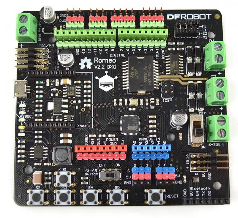
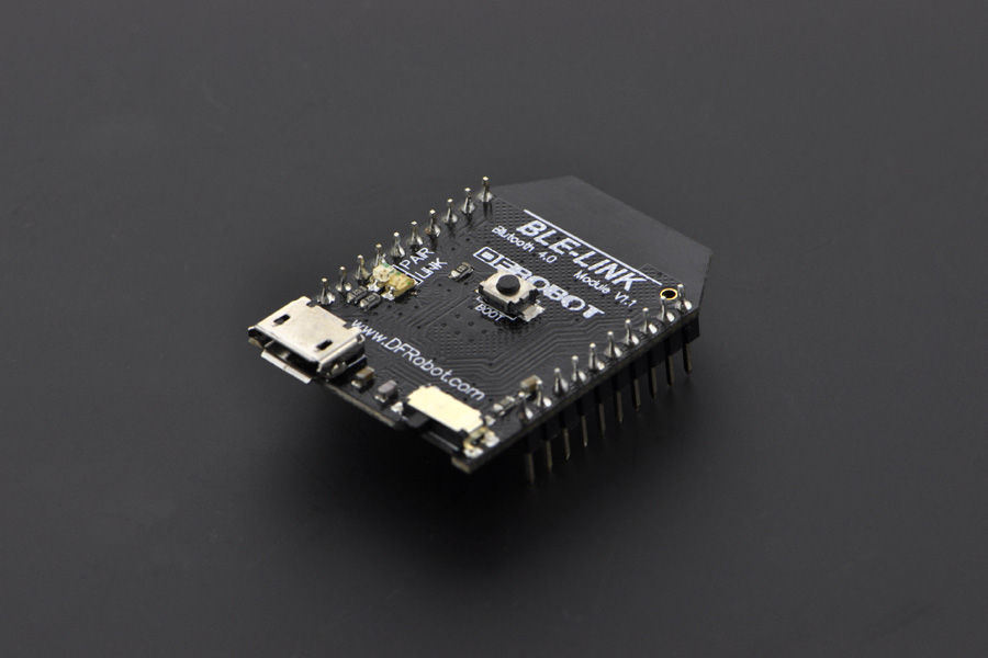
I use Bluno Bee (https://www.dfrobot.com/product-1073.html) from DFRobot for the RF module on the Romeo board. This module has a serial BLE network stack. You can attach it to the board and listen for incoming messages from serial pins. Bluno Bee has the same pin model as the XBee module. You can see it here:
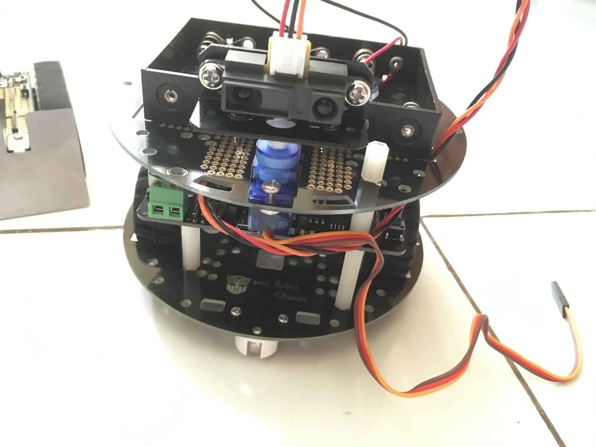
Put the Bluno Bee module into the MiniQ Discover Arduino robot on the Romeo board. You also need another Bluno Bee that is attached to your computer through a micro-USB cable. You can see my implementation of the robot kit here:
Now we'll continue to develop a program to enable our robot to be controlled from a computer. Make sure you've turned off the robot. Using a micro-USB cable attached to the Romeo board, you can write a sketch program.
Open the Arduino software and write the following complete program:
//Standard PWM DC control
int E1 = 5; //M1 Speed Control
int E2 = 6; //M2 Speed Control
int M1 = 4; //M1 Direction Control
int M2 = 7; //M1 Direction Control
void stop(void) //Stop
{
Serial.println("stop");
digitalWrite(E1,LOW);
digitalWrite(E2,LOW);
}
void advance(char a,char b) //Move forward
{
Serial.println("advance");
analogWrite (E1,a); //PWM Speed Control
digitalWrite(M1,HIGH);
analogWrite (E2,b);
digitalWrite(M2,HIGH);
}
void back_off (char a,char b) //Move backward
{
Serial.println("back_off");
analogWrite (E1,a);
digitalWrite(M1,LOW);
analogWrite (E2,b);
digitalWrite(M2,LOW);
}
void turn_L (char a,char b) //Turn Left
{
Serial.println("turn_L");
analogWrite (E1,a);
digitalWrite(M1,LOW);
analogWrite (E2,b);
digitalWrite(M2,HIGH);
}
void turn_R (char a,char b) //Turn Right
{
Serial.println("turn_R");
analogWrite (E1,a);
digitalWrite(M1,HIGH);
analogWrite (E2,b);
digitalWrite(M2,LOW);
}
void setup(void)
{
int i;
for(i=4;i<=7;i++)
pinMode(i, OUTPUT);
Serial.begin(115200); //Set Baud Rate
Serial.println("Run keyboard control");
Serial1.begin(115200); //Set Baud Rate
}
void loop(void)
{
if(Serial1.available()){
char val = Serial1.read();
if(val != -1)
{
switch(val)
{
case 'w'://Move Forward
Serial.println("Move Forward");
advance (100,100); //move forward
break;
case 's'://Move Backward
Serial.println("Move Backward");
back_off (100,100); //move back
break;
case 'a'://Turn Left
Serial.println("Turn Left");
turn_L (100,100);
break;
case 'd'://Turn Right
Serial.println("Turn Right");
turn_R (100,100);
break;
case 'z':
Serial.println("Hello");
break;
case 'x':
stop();
break;
}
}
else stop();
}
}
Save this sketch as ArduinoRobotDemo. Now you can build and upload it to the Romeo board.
Now your robot should switch to battery power. Your robot should be ready to receive a command from the computer.
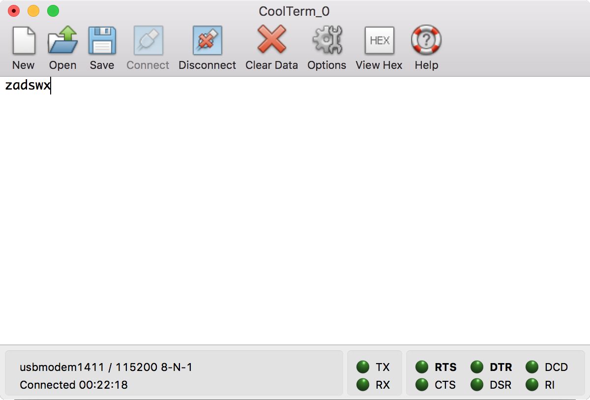
Since one Bluno Bee module is connected to a computer, you can use any serial tool to send messages to Bluno Bee. I use CoolTerm (http://freeware.the-meiers.org) for testing.
Connect the CoolTerm application to the serial port of Bluno Bee. By default, it uses a baud rate of 115200. Based on our sketch program, you can use these keys to move the robot:
W to move forward
S to move backward
A to move left
D to move right
Z to print hello to the serial port
X to stop
You can see my CoolTerm application output here:
To move properly, our robot shouldn't be hindered by obstacles. A common solution to detect obstacles is to use an ultrasonic sensor. A sample sensor implementation is HC-SR04. You can get it from SparkFun: https://www.sparkfun.com/products/13959. You can see it here:

The HC-SR04 sensor has four pins: VCC (Power), Trig (Trigger), Echo (Receive), and GND (Ground), which are easy to connect to Arduino and Raspberry Pi.
Another sensor is the IR distance sensor. A sample sensor implementation is the Sharp GP2Y0A21 IR Distance Sensor, https://www.dfrobot.com/product-328.html, from DFRobot. Since I'm using the MiniQ Discovery Arduino robot, this sensor can be attached directly to the robot shield. You can see this here:
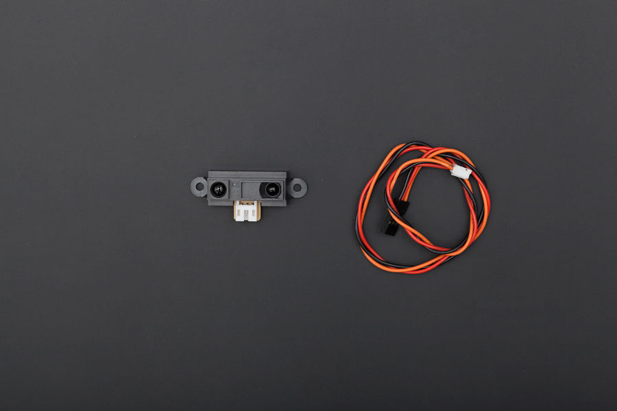
The GP2Y0A21 sensor has three pins: VCC, GND, and Signal. The Signal pin of GP2Y0A21 can be connected to analog pins from the Arduino board.
We can also scan obstacles around the robot. In this case, we need a servo motor and attach our sensor to the servo motor. You can get it from DFRobot on this site: https://www.dfrobot.com/product-255.html. You can also can see this kit here:
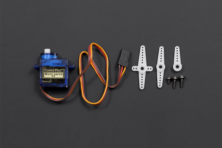
In general, a servo has three wires with the following pinout information:
Brown wire is GND
Red wire is VCC
Orange wire is the signal line
You can connect a servo to Arduino through PWM pins.
To attach the Sharp GP2Y0A21 IR distance sensor to a servo motor, you need a mounting bracket like this product (https://www.dfrobot.com/product-127.html):
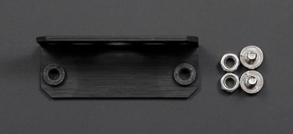
DFRobot also provides a complete kit, which consists of a Sharp GP2Y0A21 sensor, servo motor, and mounting bracket. You can check it out on https://www.dfrobot.com/product-715.html.
For this demo, we will wire it as follows:
GP2Y0A21 VCC to Arduino 3.3V
GP2Y0A21 GND to Arduino GND
GP2Y0A21 Signal to Arduino analog pin A0
Servo VCC to Arduino 5V
Servo GND to Arduino GND
Servo Signal to Arduino digital pin 9
After you've attached the sensor, mounting, and servo motor to the robot, you can start developing your sketch program. You can see my implementation here:
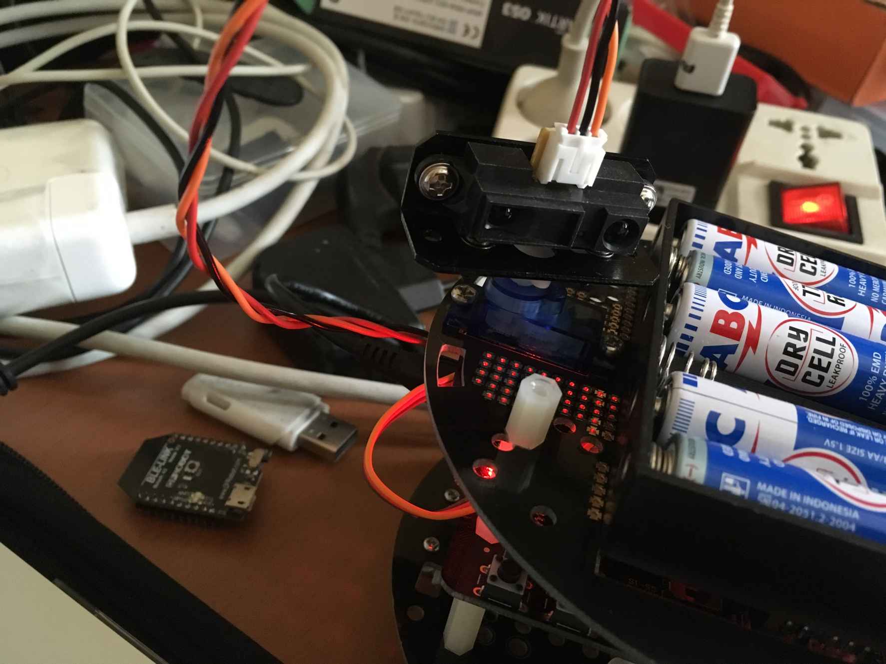
In the sketch program, we can access the servo motor using the Servo library. For further information on the Servo library, I recommend you read https://www.arduino.cc/en/Reference/Servo.
We will develop a sketch program to scan the obstacle distance around a robot. We'll move our sensor from 0 to 180 degrees through the servo motor.
Now you can open the Arduino software and write this sketch program:
#include <Servo.h>
Servo servo;
#define Svo_Pin 9
#define GP2Y0A21 A0
void setup() {
servo.attach(Svo_Pin);
Serial.begin(9600);
}
void loop() {
for (int i=0;i<180;i++)
{
servo.write(i);
uint16_t value = analogRead(GP2Y0A21);
uint16_t range = get_gp2d12(value);
Serial.print("Distance. Value: ");
Serial.print(value);
Serial.print(". Range: ");
Serial.print(range);
Serial.println(" mm");
delay(200);
}
delay(2000);
}
uint16_t get_gp2d12 (uint16_t value) {
if (value < 10) value = 10;
return ((67870.0 / (value - 3.0)) - 40.0);
}
Save this sketch program as ArduinoDisctanceScanner.
Build and upload the program to your Arduino board. You can open the Serial Monitor tool from Arduino to see the following program output:
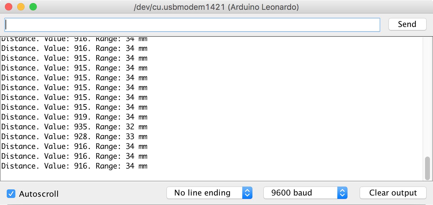
First, we declare our sensor and servo. Then, we initialize our setup() function.
#include <Servo.h>
Servo servo;
#define Svo_Pin 9
#define GP2Y0A21 A0
void setup() {
servo.attach(Svo_Pin);
Serial.begin(9600);
}
In the loop() function, we move our servo from degree 0 to 180. On each degree change, we read a distance value from the sensor. Then, we calculate the distance by calling the get_gp2d12() function, defined in this sketch. Lastly, we print the resulting measurement to the serial port.
void loop() {
for (int i=0;i<180;i++)
{
servo.write(i);
uint16_t value = analogRead(GP2Y0A21);
uint16_t range = get_gp2d12(value);
Serial.print("Distance. Value: ");
Serial.print(value);
Serial.print(". Range: ");
Serial.print(range);
Serial.println(" mm");
delay(200);
}
delay(2000);
}
To calculate a distance, we can refer to the datasheet. We'll implement the get_gp2d12() function to obtain a distance value:
uint16_t get_gp2d12 (uint16_t value) {
if (value < 10) value = 10;
return ((67870.0 / (value - 3.0)) - 40.0);
}
Designing and implementing an autonomous robot needs a lot of work. The biggest challenge of an autonomous robot is being movement and navigation and how to achieve objectives.
An autonomous robot runs on its own accord. This is challenging because we need to make our robot decide how it moves. From an artificial intelligence perspective, we can classify two models: supervised and unsupervised.
A supervised autonomous robot requires some objectives or guidelines to achieve its goals. On the other hand, an unsupervised autonomous robot can learn from its experiences and then make own decision based on certain conditions.
To build an autonomous robot for movement and navigation, we can design our algorithm as follows:
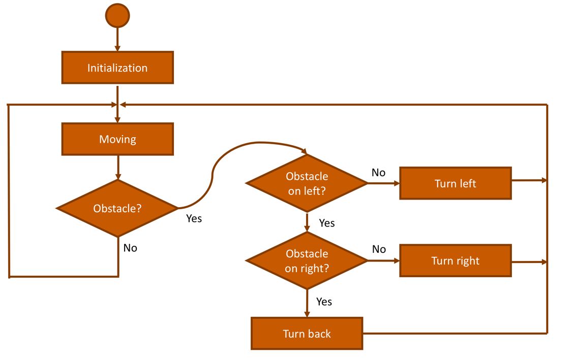
Before starting, a robot will initialize all parameters included for its sensors and motors. Then, we'll start by moving it in a random direction. While moving, the robot may detect an obstacle. If one is found, the robot will change direction.
In this scenario, we aren't defining the the goal of the autonomous robot. An example goal could be if it finds a star sign, the robot should stop and power off. You can define your own decisions and goals.
An autonomous firefighter robot is basically an autonomous robot with an objective of sprinkling water on a fire. To achieve this goal, the robot will move around to find a fire source. While moving, a robot should handle obstacle problems.
A sample design of an autonomous firefighter robot can be seen here:
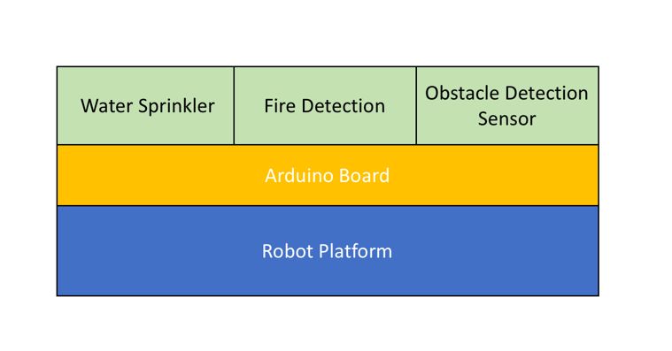
The robot should have a water sprinkler module and fire and obstacle detection sensors. The robot platform can be based in Arduino, Raspberry Pi, or other MCU boards.
The idea of an autonomous robot for firefighting is similar in behavior to a common autonomous robot, but with additional features to detect fires and sprinkle water on them.
We can modify our autonomous robot design from the previous section for a firefighter robot scenario. You can see the modified design here:
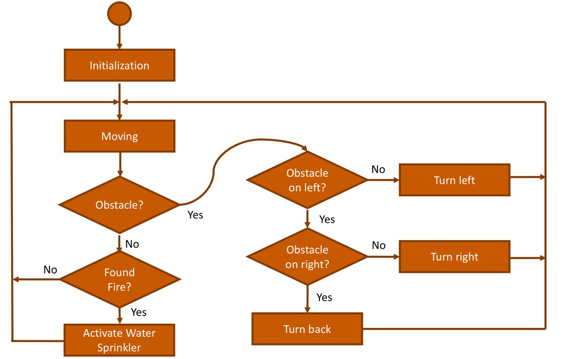
We've added fire detection and water sprinkling to our algorithm. When the robot is moving, it should detect obstacles and fire. If it finds a fire, it should sprinkle water on it to put it out.
We learned about robot platforms in this chapter. Then, we learned about firefighter robots that move and detect a fire source and obstacles. Lastly, we design an autonomous robot for firefighting.
In the next chapter, we will explore multi-robot cooperation using swarm intelligence.