Coordinating autonomous robots is challenging: each robot has its own intelligence system. These robots try to perform self-managed activities to achieve a particular goal. In this chapter, we'll learn how to work and deal with multiple robots in order to execute their goals.
We will learn about the following topics:
Introducing multi-robot cooperation
Learning about swarm intelligence
Implementing a mesh network for a multi-robot scenario
XBee development for Arduino
Designing a multi-robot cooperation model using swarm intelligence
Let's start!
Communicating and negotiating among robots is challenging. We should ensure our robots address collision while they are moving. Meanwhile, these robots should achieve their goals collectively.
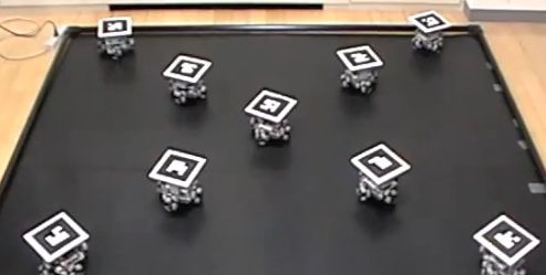
For example, Keisuke Uto has created a multi-robot implementation to create a specific formation. They take input from their cameras. Then, these robots arrange themselves to create a formation. To get the correct robot formation, this system uses a camera to detect the current robot formation. Each robot has been labelled so it makes the system able to identify the robot formation.
By implementing image processing, Keisuke shows how multiple robots create a formation using multi-robot cooperation. If you are interested, you can read about the project at https://www.digi.com/blog/xbee/multi-robot-formation-control-by-self-made-robots/. Here they are in action:

Image source: https://www.digi.com/blog/xbee/multi-robot-formation-control-by-self-made-robots/
For another example, can have soccer matches in which the players are not human; they are all robots. Such a competition can use custom robots or existing commercial robots such as the Nao robot, https://www.ald.softbankrobotics.com/en/robots/nao. You can see Nao robots in a soccer match here:

Image source: http://www.robocup2014.org/?p=893
As we know, a robot soccer game involves robots, and they need skill and knowledge in order to win. The robot should detect the ball and score goals. Meanwhile, each robot should perform group cooperation. Addressing collision among robots and passing the ball to its group are challenging in this area.
Swarm intelligence is inspired by the collective behavior of social animal colonies such as ants, birds, wasps, and honey bees. These animals work together to achieve a common goal.
Swarm intelligence phenomena can be found in our environment. You can see swarm intelligence in deep-sea animals, shown in the following image of a school of fish in formation that was captured by a photographer in Cabo Pulmo:

Image source: http://octavioaburto.com/cabo-pulmo
Using information from swarm intelligence studies, swarm intelligence is applied to coordinate among autonomous robots. Each robot can be described as a self-organization system. Each one negotiates with the others on how to achieve the goal.
There are various algorithms to implement swarm intelligence. I recommend you read textbooks about it. Some math and statistics are applied for implementing swarm intelligence. The following is a list of swarm intelligence types that researchers and developers apply to their problems:
Particle swarm optimization
Ant system
Ant colony system
Bees algorithm
Bacterial foraging optimization algorithm
The Particle Swarm Optimization (PSO) algorithm is inspired by the social foraging behavior of some animals such as the flocking behavior of birds and the schooling behavior of fish. A sample of PSO algorithm in Python can be found at https://gist.github.com/btbytes/79877. This program needs the numpy library. numpy (Numerical Python) is a package for scientific computing with Python. You computer should has installed Python. If not, you can download and install on this site, https://www.python.org. If your computer does not have numpy , you can install it by typing this command in the terminal (Linux and Mac platforms):
$ pip install numpy
For Windows platform, please install numpy refer to this https://www.scipy.org/install.html.
You can copy the following code into your editor. Save it as ch07_pso.py and then run it on your computer using terminal:
from numpy import array
from random import random
from math import sin, sqrt
iter_max = 10000
pop_size = 100
dimensions = 2
c1 = 2
c2 = 2
err_crit = 0.00001
class Particle:
pass
def f6(param):
'''Schaffer's F6 function'''
para = param*10
para = param[0:2]
num = (sin(sqrt((para[0] * para[0]) + (para[1] * para[1])))) * \
(sin(sqrt((para[0] * para[0]) + (para[1] * para[1])))) - 0.5
denom = (1.0 + 0.001 * ((para[0] * para[0]) + (para[1] * para[1]))) * \
(1.0 + 0.001 * ((para[0] * para[0]) + (para[1] * para[1])))
f6 = 0.5 - (num/denom)
errorf6 = 1 - f6
return f6, errorf6;
#initialize the particles
particles = []
for i in range(pop_size):
p = Particle()
p.params = array([random() for i in range(dimensions)])
p.fitness = 0.0
p.v = 0.0
particles.append(p)
# let the first particle be the global best
gbest = particles[0]
err = 999999999
while i < iter_max :
for p in particles:
fitness,err = f6(p.params)
if fitness > p.fitness:
p.fitness = fitness
p.best = p.params
if fitness > gbest.fitness:
gbest = p
v = p.v + c1 * random() * (p.best - p.params) \
+ c2 * random() * (gbest.params - p.params)
p.params = p.params + v
i += 1
if err < err_crit:
break
#progress bar. '.' = 10%
if i % (iter_max/10) == 0:
print '.'
print '\nParticle Swarm Optimisation\n'
print 'PARAMETERS\n','-'*9
print 'Population size : ', pop_size
print 'Dimensions : ', dimensions
print 'Error Criterion : ', err_crit
print 'c1 : ', c1 print 'c2 : ', c2
print 'function : f6'
print 'RESULTS\n', '-'*7
print 'gbest fitness : ', gbest.fitness
print 'gbest params : ', gbest.params
print 'iterations : ', i+1
## Uncomment to print particles
for p in particles:
print 'params: %s, fitness: %s, best: %s' % (p.params, p.fitness, p.best)
You can run this program by typing this command:
$ python ch07_pso.py
You can see a sample of my program output here:
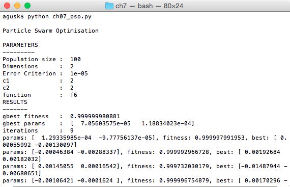
This program will generate PSO output parameters based on input. You can see PARAMETERS value on program output. At the end of codes, we can print all PSO particle parameter while iteration process.
To implement multi-robot cooperation, we need a communication medium. In general, RF communication is chosen by researchers and makers to exchange data among robots. In this book, we will use XBee modules from Digi International to establish RF communication.
XBee modules are RF modules that are manufactured by Digi International. There are various XBee modules that we can use in our robots. One of the XBee modules is the XBee Series 1 that supports the IEEE 802.15.4 protocol. This module has features to address multi-point packets. For further information about the XBee Series 1, you can visit this site: https://www.digi.com/products/xbee-rf-solutions/2-4-ghz-modules/xbee-802-15-4.
XBee modules can be found in several online stores and even in your local stores. The following image is of the XBee Pro 60mW PCB Antenna - Series 1 that is available on SparkFun: https://www.sparkfun.com/products/11216. Another product model that can also be used is the XBee 1mW Trace Antenna - Series 1 (https://www.sparkfun.com/products/11215).
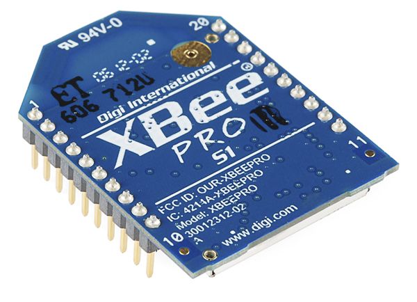
Basically, the XBee Series 1 supports point-to-point networks but we can configure it using DigiMesh firmware in order to work with a mesh network. I will explain how to configure the XBee Series 1 to use DigiMesh firmware in the next section.
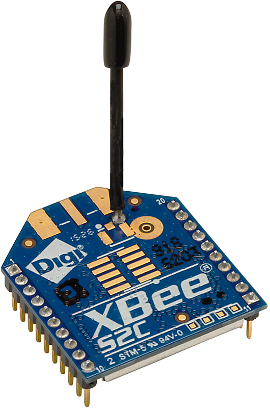
Another option is you can buy the XBee DigiMesh and XBee S2C or the latest of XBee Series 2 module to work with mesh networks. For further information about the XBee DigiMesh, you can read https://www.digi.com/products/xbee-rf-solutions/2-4-ghz-modules/xbee-digimesh-2-4. Here is what the XBee S2C looks like:
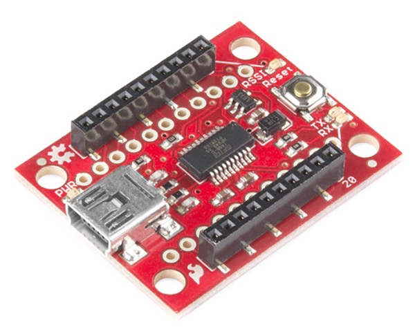
These XBee modules have their own header pins so if we want to access these pins, we'll need an XBee shield or breakout. There are many XBee shields that fit your board. They are also available for use through PCs via XBee USB, for example, SparkFun XBee Explorer USB: https://www.sparkfun.com/products/11812. You can put an XBee module into this breakout. Then, you can connect it to your computer through a USB cable. You can see the SparkFun XBee Explorer USB here:
Digi has provided a software tool to configure all XBee modules. It's called XCTU. It can be downloaded from https://www.digi.com/products/xbee-rf-solutions/xctu-software/xctu. Download the version for your OS platform. Here's what it looks like:
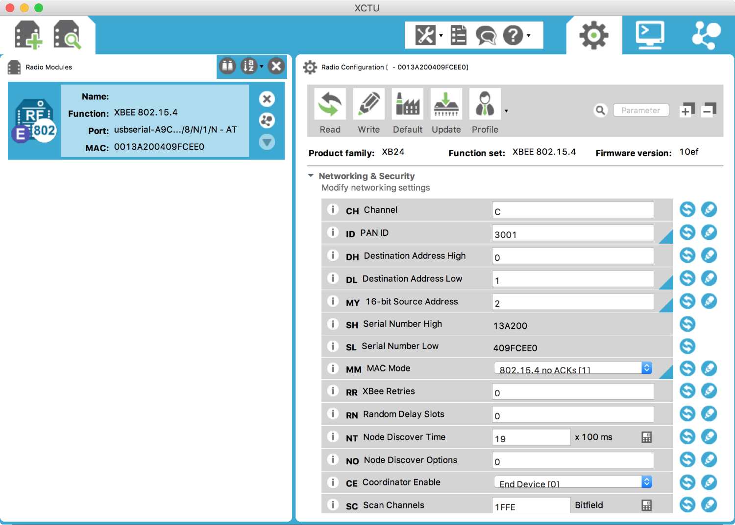
Make sure all XBee modules have installed the XBee Digimesh firmware in order to build a mesh network.
After the XBee module is attached to an XBee breakout USB and connected to a computer, you can add it to the XCTU application. If you have an XBee series 1, you should update your XBee modules with XBee Digimesh. Select the latest firmware for the XB24-DM firmware model, as shown in the following screenshot, on the updated firmware dialog:
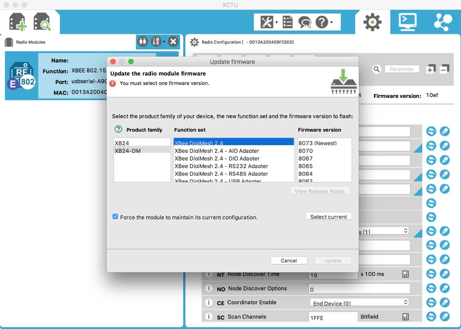
Installing Digimesh firmware on XBee modules has its benefits. We don't need a coordinator in a network. We only need to define our network ID for network identity.
In this section, we'll develop a Python application to show how to communicate between XBee modules. We need two XBee modules or more to implement our demo. We will implement a mesh network like the following for our demo:
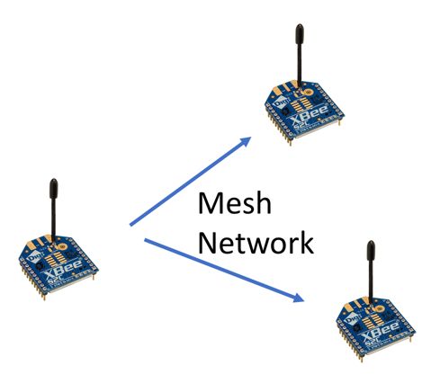
All XBee modules should already have XBee Digimesh firmware installed. Now we'll configure our mesh network.
First, we define a network ID for our mesh network. We can do this using XCTU. You can open each XBee module in the XCTU application. Then, we'll set a network ID (ID) in XCTU: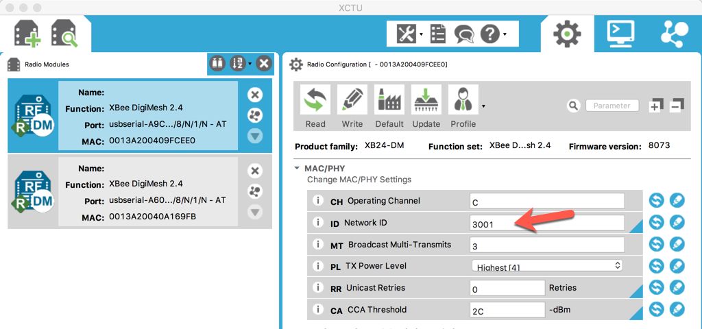
Further, you also need to configure the Baud Rate (BD) as 9600 [3] and set the API Enable value to API Mode with Escapes [2]. These settings can be seen here:
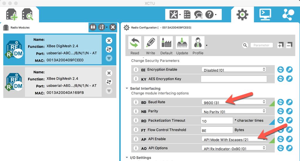
After changing these XBee parameters in XCTU, you can write these changes to the XBee module by clicking on the Write icon. Close XCTU if you are done.
Now we can develop our Python application. We'll use the xbee library for Python. You can find it at https://pypi.python.org/pypi/XBee. To install this library on your computer, you can use pip. Type this command:
$ pip install xbee
We'll develop two programs, an XBee reader and an XBee sender.
The XBee reader application will listen for all incoming messages. Once the XBee module receives a message, the application will print the message to terminal. Create a Python file called ch07_xbee_reader.py and paste this program into it:
import time
from xbee import DigiMesh
import serial
#PORT = 'COM8'
PORT = '/dev/cu.usbserial-A601F21U'
BAUD_RATE = 9600
def ByteToHex(byteStr):
return ''.join(["%02X" % ord(x) for x in byteStr]).strip()
def decodeReceivedFrame(data):
source_addr = ByteToHex(data['source_addr'])
rf_data = data['data']
options = ByteToHex(data['options'])
return [source_addr, rf_data, options]
# Open serial port
ser = serial.Serial(PORT, BAUD_RATE)
# Create API object
xbee = DigiMesh(ser, escaped=True)
import pprint
pprint.pprint(xbee.api_commands)
while True:
try:
data = xbee.wait_read_frame()
decodedData = decodeReceivedFrame(data)
print(decodedData)
except KeyboardInterrupt:
break
xbee.halt()
ser.close()
Change the PORT value based on your attached XBee serial port.
The next step is to develop the XBee sender application. For our demo, we'll send the messages Hello XBee 2 to all XBee modules on the mesh network with a certain ID. You can write the following program:
import time
from xbee import DigiMesh
import serial
#PORT = 'COM7'
PORT = '/dev/cu.usbserial-A9CNVHXX'
BAUD_RATE = 9600
# Open serial port
ser = serial.Serial(PORT, BAUD_RATE)
# Create API object
xbee = DigiMesh(ser, escaped=True)
import pprint
pprint.pprint(xbee.api_commands)
# xbee with long address
XBEE2_ADDR_LONG = "\x00\x00\x00\x00\x00\x00\xFF\xFF"
while True:
try:
print "send data"
xbee.tx(frame='0x1', dest_addr=XBEE2_ADDR_LONG, data='Hello XBee 2')
time.sleep(1)
except KeyboardInterrupt:
break
xbee.halt()
ser.close()
Change the PORT value based on your XBee serial port. Save this program into a file called ch07_xbee_sender.py.
Now you can start running your XBee reader application. Type this on a computer to which the XBee module for the reader application is attached:
$ python ch07_xbee_reader.py
Then, run the XBee sender application by typing this command:
$ python ch07_xbee_sender.py
You should see incoming messages in the XBee reader application, shown here:
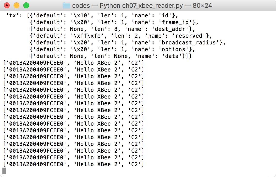
You'll also see messages in the XBee sender application. Sample program output can be seen here:

All XBee applications should import the xbee DigiMesh library for Python. We can set the serial port for each XBee module. You can change this serial port to one of your liking.
import time
from xbee import DigiMesh
import serial
#PORT = 'COM7'
PORT = '/dev/cu.usbserial-A9CNVHXX'
BAUD_RATE = 9600
# Open serial port
ser = serial.Serial(PORT, BAUD_RATE)
# Create API object
xbee = DigiMesh(ser, escaped=True)
import pprint
pprint.pprint(xbee.api_commands)
In the XBee reader application, we listen for incoming messages from XBee by calling the wait_read_frame() function. After a message is received, we decode the data by calling the decodeReceivedFrame() function.
while True:
try:
data = xbee.wait_read_frame()
decodedData = decodeReceivedFrame(data)
print(decodedData)
except KeyboardInterrupt:
break
To decode the packet frame, we parse the JSON data using the decodeReceiveFrame() function. We declare the following functions:
def ByteToHex(byteStr):
return ''.join(["%02X" % ord(x) for x in byteStr]).strip()
def decodeReceivedFrame(data):
source_addr = ByteToHex(data['source_addr'])
rf_data = data['data']
options = ByteToHex(data['options'])
return [source_addr, rf_data, options]
Then, we send data on the XBee sender application. We set the receiver address to FF. That's a broadcast address so all XBees will receive messages on the same mesh network. To send data, we call the tx() function.
# xbee with long address
XBEE2_ADDR_LONG = "\x00\x00\x00\x00\x00\x00\xFF\xFF"
while True:
try:
print "send data"
xbee.tx(frame='0x1', dest_addr=XBEE2_ADDR_LONG, data='Hello XBee 2')
time.sleep(1)
except KeyboardInterrupt:
break
If your robot platform uses Arduino as the MCU model, we can use XBee on the Arduino board. Several Arduino shields for XBee are available as well. Some robot platforms based on Arduino even provide an XBee shield in the board.
In this section, we'll develop an application to communicate between our computer and an XBee module on an Arduino board. We need two XBee modules for this demo.
We're using a mesh network for communication among XBees. In the previous section, we applied DigiMesh firmware to our XBee modules. In this demo, we'll develop an application to send data from XBee on an Arduino to XBee on a computer.
First, we configure all XBee modules using XCTU. After opening XBee using XCTU, we can start to configure it. Set Destination Address Low (DL) with FFFF. You can see it here:
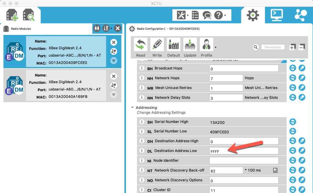
You also need to set API Enable (AP) as Transparent Mode [0], as shown in the following figure. If finished, you can write all changes to the XBee:
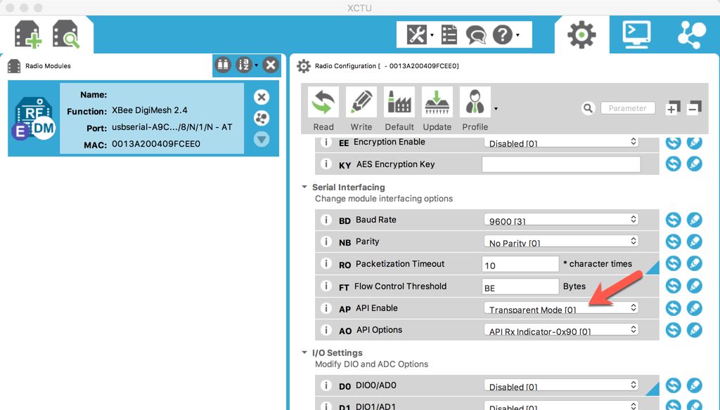
Implement these steps for both XBee modules.
The next step is to develop a program. We'll write a sketch program for Arduino. In this case, we attach our XBee to the Arduino through an XBee shield. This means that the XBee connects to the Arduino via serial pins (digital pin 0 and 1). We'll use the serial object to communicate with the Arduino.
Here is the complete sketch program:
void setup() {
// start serial
Serial.begin(9600);
while (!Serial) ;
// Arduino Leonardo
// Serial1.begin(9600);
// while (!Serial1) ;
}
void loop() {
//Serial1.println("hello"); // Leonardo
Serial.println("hello");
delay(1000);
}
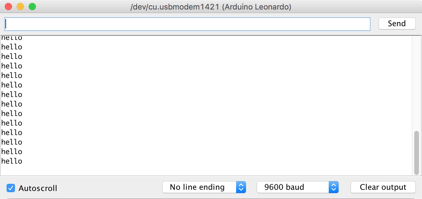
Save this program as ArduinoXBee. This program will send the message hello. If you use Arduino Leonardo, uncomment the commented section because Arduino Leonardo uses Serial1 to communicate with XBee.
Compile and upload the sketch program to your Arduino board. After this, you can open the Serial Monitor tool from the Arduino software.
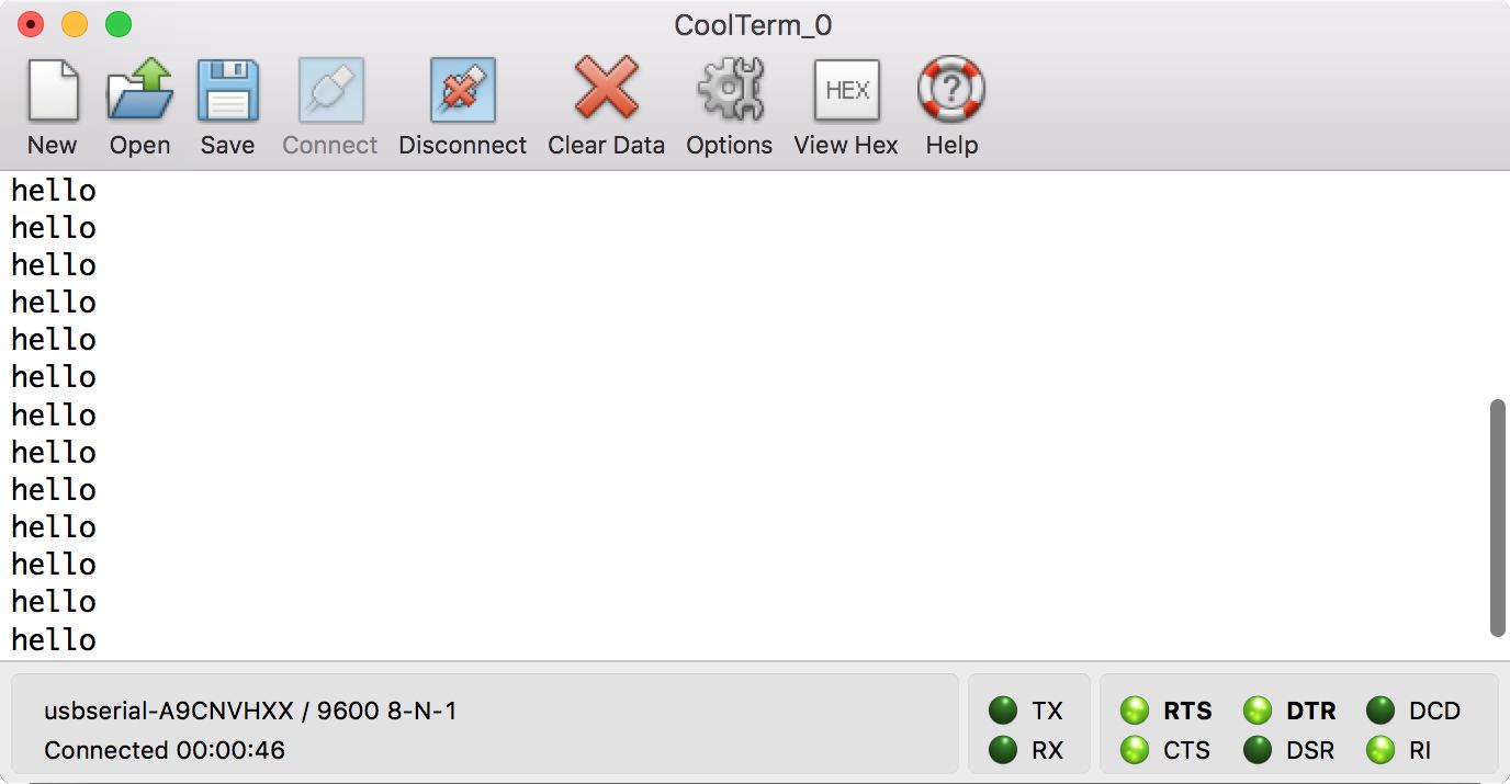
You should also run a serial application such as CoolTerm and open the XBee module to see incoming messages from the Arduino-mounted XBee.
You can see messages from the Arduino in Serial Monitor:
In CoolTerm as well, you can see incoming messages from the Arduino:
In the previous section, we learned how to communicate with XBee on Arduino through the Serial object. Our XBee works in API Enabled (AP) 0, transparent mode.
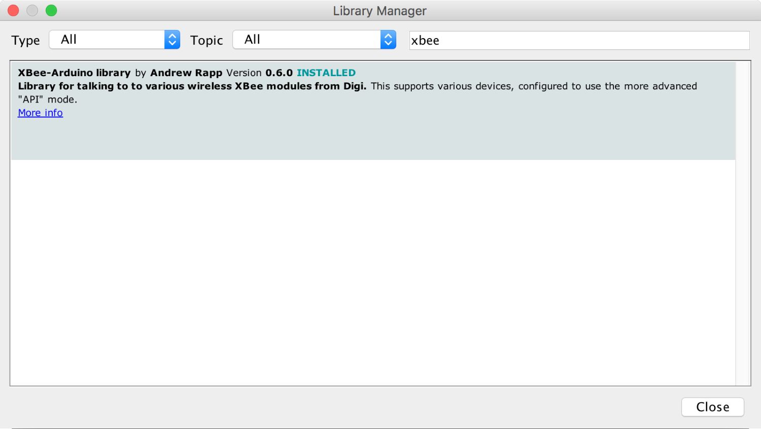
You also worked with the XBee in AP 2 mode, so you can control all parameters in XBee, including the destination address of XBee receivers. For sketch programs, we can utilize the Xbee-Arduino library, https://github.com/andrewrapp/xbee-arduino. This library supports XBee Series 1 and Series 2. You also can install it on the Arduino via Library Manager:
Another library option is the Bee library: https://github.com/kmark/Bee. This library is designed for DigiMesh firmware.
To get started, I recommend you try program samples from these libraries.
A multi-robot cooperation model enables some robots to work collectively to achieve a specific purpose. Having multi-robot cooperation is challenging. Several aspects should be considered in order to get an optimized implementation. The objective, hardware, pricing, and algorithm can have an impact on your multi-robot design.
In this section, we will review some key aspects of designing multi-robot cooperation. This is important since developing a robot needs multi-disciplinary skills.
The first step to developing multi-robot swarm intelligence is to define the objectives. We should state clearly what the goal of the multi-robot implementation is. For instance, we can develop a multi-robot system for soccer games or to find and fight fire.
After defining the objectives, we can continue to gather all the material to achieve them: robot platform, sensors, and algorithms are components that we should have.
The robot platform is the MCU model that will be used. There are several MCU platforms that you use for a multi-robot implementation. Arduino, Raspberry Pi, ESP8266, ESP32, TI LaunchPad, and BeagleBone are samples of MCU platforms that can probably be applied for your case.
Sometimes, you may nee to consider the price parameter to decide upon a robot platform. Some researchers and makers make their robot devices with minimum hardware to get optimized functionalities. They also share their hardware and software designs. I recommend you visit Open Robotics, https://www.osrfoundation.org, to explore robot projects that might fit your problem.
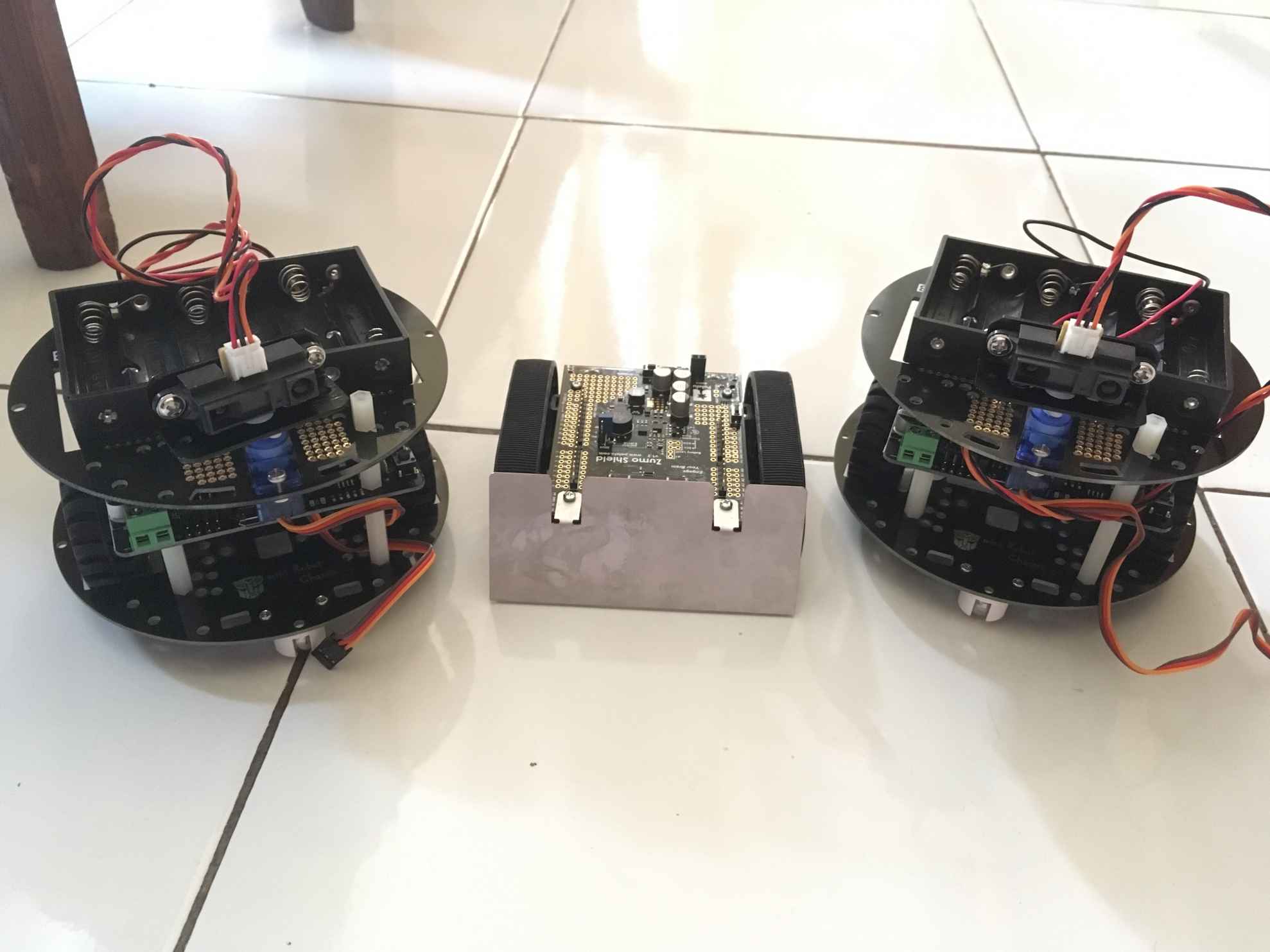
Alternatively, you can consider using robot kits. Using a kit means you don't need to solder electronic components. It is ready to use. You can find robot kits in online stores such as Pololu (https://www.pololu.com), SparkFun (https://www.sparkfun.com), DFRobot (https://www.dfrobot.com), and Makeblock (http://www.makeblock.com).
You can see my robots from Pololu and DFRobot here:
The choice of algorithm, especially for swarm intelligence, should be connected to what kind of robot platform is used. We already know that some hardware for robots have computational limitations. Applying complex algorithms to limited computation devices can drain the hardware battery. You must research the best parameters for implementing multi-robot systems.
Implementing swarm intelligence in swarm robots can be described as in the following figure. A swarm robot system will perform sensing to gather its environmental information, including detecting peer robot presence.
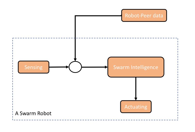
By combining inputs from sensors and peers, we can actuate the robots based on the result of our swarm intelligence computation. Actuation can be movement and actions.
We explored designing multi-robot systems. Key aspects of communication for robots were also reviewed. This chapter can help you get practice in developing several types of robot hardware to build swarm robots. Research should be done to achieve the best performance for a multi-robot system.
Since this book is in the form of projects, it goes without saying that you are required to have certain pieces of hardware to actually build the projects provided in this book. Here is a list of all the required components along with their Amazon hyperlinks:
|
Units |
Components |
Type |
Description |
Manufacturers |
URLs |
|
1 |
Adafruit WICED WiFi Feather |
Adafruit WICED WiFi Feather |
WiFi Microcontroller Development Board |
Adafruit Industries |
|
|
1 |
MB-102 |
Solderless breadboard |
Solderless breadboard, power supply, and jumper wires |
NA |
|
|
1 |
JMPR |
Dupont Jumper Wires |
Haitronic 120pcs 20cm length Jumper Wires/dupont cable Multicolored(10 color) 40pin M to F, 40pin M to M, 40pin F to F for Breadboard / Arduino based / DIY/ raspberry Pi 2 3/Robot Ribbon Cables Kit |
NA |
|
|
1 |
REED SWITCH |
Winomo Magnetic Door Window Contact |
Magnetic door switches |
Winomo |
|
|
1 |
Pi3 |
Raspberry Pi 3 Camera Kit |
Raspberry Pi 3 Complete Camera Kit -- Includes Raspberry Pi 3 and 5MP Camera Module |
Vilros |
|
|
3 |
DHT22 |
DHT22 Temperature Sensor |
Gikfun DHT22 AM2302 Temperature And Humidity Sensor for Arduino EK1196_ |
Gikfun |
|
|
1 |
OV2640 |
ArduCam |
Arducam Mini Module Camera Shield with OV2640 2 Megapixels Lens for Arduino UNO Mega2560 Board |
Arducam |