Informatica Tutorial on Transformations
Posted by Superadmin on July 01 2022 05:41:28
Informatica Tutorial on Transformations
A transformation is a part of Informatica Mapping, which transforms or modifies the data as per the selected transformation. This section of Informatica tutorial covers the list of available Transformations with practical examples.
- List of Transformations
- Aggregator Transformation
- Expression Transformation
- Filter Transformation
- Java Transformation
- Joiner Transformation
- Normal Join
- Master Outer Join
- Detail Outer Join
- Full Outer Join
- Lookup Transformation
- Lookup Transformation
- Unconnected Lookup Transformation
- Normalizer Transformation
- Rank Transformation
- Rank Transformation with Group By
- Router Transformation
- Sequence Generator Transformation
- Sorter Transformation
- Sorter Transformation – Remove Duplicates
- Source Qualifier Transformation
- SQL Transformation
- Stored procedure Transformation
- Transaction Control Transformation
- Union Transformation
- Update Strategy Transformation
- Update Strategy using Session Properties
- Example for Update Strategy
- XML Generator Transformation
- XML Parser Transformation
- XMLSource Qualifier Transformation
- Pre SQL and Post SQL
Informatica Transformations
Informatica Transformations are repository Objects that are used to perform aggregations, sorting, merging, modifying, distributing, etc., while passing data through them.
The Power Center Designer provides a set of transformations in Informatica that perform specific functions. For example, Sorter transformation will sort the input fields based on a specified field.
A transformation is a part of Informatica Mapping, which transforms or modifies the data as per the selected transformation. This section covers the list of available ones with practical examples.
Informatica transformations can divide into two types: Active or Passive. We can further divide them based on the connectivity in mapping: Connected and Unconnected Transformations.
An active type of transformation in Informatica can change the number of rows that pass through it. For example, if the input rows do not meet the specified expression, then those rows will not move to the target.
The Informatica passive transformation does not change the number of rows passing through it.
Within an Informatica Mapping, if a transformation is connected to another or connected directly to the target table, it is called Connected.
All the active and passive can call connected transformations in Informatica, and they can receive / or provide multiple input ports.
Within the Mappings, if the Informatica transformation does not connect to others, we can call it Unconnected. It means it is neither connected to Source nor the target.
Unconnected Lookup is the best example of Informatica Unconnected.
Before we get into the list of Informatica transformations and their definitions, let me open my Power Center Designer to display the available list in mappings:
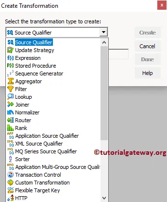
and few more

The following are a list of Informatica transformations that are available to transform data. I suggest you click on the URL (red color links) to navigate to the required transformation and find the example with a detailed explanation.
| Transformations | Type | Description |
| Aggregator |
Active / Connected |
It is used to perform Aggregate calculations such as SUM, MIN, COUNT etc. |
| Application Source Qualifier |
Active / Connected |
It represents the rows that the Integration Service reads from an application. |
| Custom |
Active or Passive / Connected |
It is used to call Procedures from DLL or shared Library |
| Data Masking |
Passive / Connected |
Use this to replace original data (sensitive data) with realistic test data. This is very useful while we are working in Non- Production environment. |
| Expression |
Passive / Connected |
Helps you to write Custom Calculation using Expression Editor. |
| External Procedure |
Passive / Connected or Unconnected |
This is used to call a procedure in a Shared Library or from the Com layer of Windows. |
| Filter |
Active / Connected |
Used to Filter the data |
| HTTP |
Passive / Connected |
Use this to connect with HTTP Server and read or update data. |
| Input |
Passive / Connected |
This is available in Mapplet Designer. Use this one to define the Input rows. |
| Java |
Active or Passive / Connected |
This is very useful to execute the code written in Java. |
| Joiner |
Active /Connected |
To Join data from multiple tables. There are four types of Joins: Normal Join, Master Outer Join, Detail Outer Join, and Full Outer Join. |
| Lookup |
Active or Passive / Connected or Unconnected |
This Informatica transformation is useful to look up data present in Relational databases, or flat files |
| Normalizer |
Active /Connected |
Use this to normalize the data (DE normalized). |
| Output |
Passive / Connected |
This is available in Mapplet Designer. Use this to define the output rows. |
| Rank |
Active /Connected |
Used to Limit the records from Top or Bottom |
| Router |
Active /Connected |
Based on the group condition, it will route the data to multiple destinations or trans. |
| Sequence Generator |
Passive / Connected |
This Informatica Transformation will generate Numeric values. We mainly use this to generate primary keys |
| Sorter |
Active /Connected |
This is used to Sort the data based on the specified Column or Key |
| Source Qualifier |
Active /Connected |
It represents the rows that the Service reads from a Flat File or Relational Database. |
| SQL |
Active or Passive / Connected |
It helps you to execute SQL Queries against a Database |
| Stored Procedure |
Passive / Connected or Unconnected |
Use this to call a stored procedure. |
| Transaction Control |
Active / Connected |
By using this you can define Commit, and Rollback Transactions |
| Union |
Active / Connected |
This is used to combine or merge data from different databases or sources. |
| Unstructured Data |
Active or Passive / Connected |
This Informatica transformation transforms data in a semi-structured or unstructured format. |
| Update Strategy |
Active /Connected |
Used to determine whether to Insert, Update, Delete, or reject Rows. |
| XML Generator |
Active /Connected |
It reads data from one or more ports and returns XML |
| XML Parser |
Active /Connected |
Reads XML file and output the data. |
| XML Source Qualifier |
Active /Connected |
It represents the records that the Integration Service reads from an XML source. |
If you want to save the above specified list of Informatica Transformations in your Mobile, then use below image

Aggregator Transformation in Informatica
The Aggregator Transformation in Informatica is one of the most used transformations in real-time. This transformation performs a function similar to the SQL Server Aggregate functions.
The Informatica Aggregator Transformation operations include the following:
- COUNT: It will count the number of values in this column. Null values are included in the count if you select (*) as the input column. Otherwise, null values ignored.
- SUM: Calculate the Sum of the Column values.
- AVG: Calculate the Average of the Column values.
- MIN: Finding the Minimum Column value.
- MAX: Finding the Maximum Column value.
- Median: Calculate the Median of the column values.
- Stddev: Calculate the Standard Deviation of the column values.
- Variance: Calculate the Variance of the column values.
In this article, we explain the steps involved in configuring the Aggregator Transformation in Informatica to perform a few of the operations, as mentioned above.
Before we start configuring the Aggregator transformation in Informatica, First connect to the repository service.
To connect with the Informatica Repository service, we have to provide the Admin Console Username and Password you specified while installing the Server.

Once you connected successfully, Please navigate to Source Analyzer and define your Sources. In this Informatica Aggregator Transformation example, we are using [Dim Geography] and [Fact Reseller Sales] from the SQL Server database as our source definitions. Please visit Database Source to understand creating source definition

Please navigate to Target Designer and define the Informatica Aggregator Transformation Target. In this example, we are using the already created (Aggregator Transformation) SQL table as our target definition. Please refer Create Target table using Source Definition article

To create a new mapping for Informatica Aggregator Transformation, Please navigate to the Mappings menu and select the Create.. option. It opens the Mapping Name window.
Here, you have to write a unique name for this mapping (m_Aggregator_Transformation) and click the OK button.

Next, Drag and drop the [Dim Geography] and [fact Reseller Sales] source definitions from the Sources folder to the mapping designer. Once you drag the source, the PowerCenter designer automatically creates the default transformation called the source qualifier.
As we all know that the [Dim Geography] and [fact Reseller Sales] tables have the Primary and Foreign key relationship. So, we removed one source qualifier and added the required fields from both tables to single source qualifier.
In order to create Aggregator Transformation in Informatica, Please navigate to Transformation menu in Menu Bar and select the Create.. option as we shown below.

Once you click on the Create.. option, Create Transformation window will open as shown below. Please select the Informatica Aggregator Transformation from the drop-down list and specify the unique name (agg_Geography_Sales) for this transformation and click on Create button

Once you click on the Create button, the Aggregator Transformation will add to the mapping designer. Please connect the Source definition with the transformation by dragging the required fields.
From the below screenshot you can observe that we are excluding the unwanted columns like Spanish Country name, Keys, IP address locator etc.

Double click on the Informatica Aggregator transformation to perform aggregations on the source. From the below screenshot you can see the list of available properties in the Transformation tab:
- Select Transformation: By default, it will select the one. you clicked on.
- Rename: This button will help you to rename the Aggregator transformation to a more meaningful name.
- Make Reusable: If you check mark this option then, it becomes the reusable transformation.
- Description: Please provide a valid description of this Informatica aggregator transformation.

Below screenshot will show you the list of available options in the Ports tab of a Informatica Aggregator Transformation:
- Port Name: List of available column names. By clicking the New column button you can add new columns and by clicking the scissors button you can delete the unwanted columns.
- I: Columns that are check-marked under this section are the Aggregator transformation Input columns.
- O: Columns that are check-marked under this section are the Aggregator transformation Output columns. If you unchecked any column then, that column will not be available to load in a target table. From the below screenshot you can observe that we unchecked this port for five columns (Unit Price, Product Standard Cost, Total Product Cost, Sales Amount and Tax Amount) because we want to restore these columns with new fields (holding the aggregated data)
- V: Please check mark this if it is variable
- Expression: Here you can write the custom expression for the particular column.
- Group By: Please checkmark the Column that you want to use for Group by, it is just like the GROUP BY Clause in SQL SELECT queries. In this example, we want to group the data by English Country Region Name, State Province Name and City.
We added 5 new columns using the New Port button. We are going to use these new columns to store the Aggregated information such as Sum, Mean, Median, Count etc..
TIP: All these new columns are output ports only so, please check mark O

Let us write the custom expression to get the information we required. To do this, Click on the arrow button beside the o_UnitPrice. This will open the Expression Editor to write a custom expression. Here, we want to find the average of the Unite Price so select the AVG() function from the list of aggregate functions.

In this Informatica Aggregator Transformation example, we are calculating the Average of Unit Price, Sum Product Standard Cost, Median of Total Product Cost, Standard Deviation of Sales Amount and Variance of Tax Amount and Group by English Country Region Then by State Province Name and Then by City.
TIP: We select some random function, we suggest you follow your business logic to get more meaningful results.

The list of available options in the Informatica Aggregator Transformation Properties tab. If your data is pre-sorted, please select the Sorted Input option.
TIP: Selecting the Sorted Input option will improve the performance of the Aggregator transformation in Informatica.

Once you finish configuring the aggregations, Click OK to close the window. Next, Drag and drop the target definition (aggregator transformation) from Targets folder to the mapping designer and connect the aggregator transformation with the target definition.
Please use the Autolink.. option to connect them.

Before we close the Mapping, Let us validate the Informatica aggregator transformation mapping by going to Mapping Menu bar and selecting the Validate option.
Once we finish creating the Mapping we have to create the workflow for it. PowerCenter Workflow manager provides two approaches to create a workflow.
In this Informatica Aggregator Transformation example, we are going to use the manually created Workflow that we created in our earlier posts. Once we created the workflow, our next step is to create a session task for our mapping.
Create a Session
There are two types of sessions:
For this Informatica Aggregator Transformation example, we are going to create Non-reusable Session. Please navigate to Tasks Menu and select the Create option to open the Create Task window. Here you have to select the Session as Task type (default) and enter a unique name (S_Aggregator_Transformation) for the session.
Once you click on the Create button, a new window called Mappings will open. Here you have to select the mapping you want to associate with this session. We are selecting the mapping (m_Aggregator_Transformation) that we created earlier (in Step 3).

Double click on the Session Task to configure it. Although we have to configure Sources, targets, and some common properties, we already explain them in Session’s article.
The Aggregator Transformation in Informatica workflow is a valid one. Now, Let us start the Workflow by navigating to Workflows menu and selecting the Start Workflow option.

Once you select the Start Informatica Aggregator Transformation Workflow option, the PowerCenter Workflow monitor will be opened to monitor the workflow. From the below screenshot you can observe that our workflow is executed without any errors.

Let us open the SQL Server Management Studio to check whether we successfully performed aggregations using the Aggregator Transformation in Informatica.

Expression Transformation in Informatica
The Expression Transformation in Informatica is a passive transformation that is used to perform non-aggregate calculations on the source data. It means you can use this Informatica Expression transformation to perform calculations on a single row. For example, you are trimming the extra spaces, data conversions, string manipulations, etc.
The following are some of the operations achieved by the expression transformation in Informatica :
- Using this expression transformation in Informatica, we can test the data before passing it to another transformation or target table using conditional statements IIF
- Data Manipulation: We can manipulate the data using built-in functions. For example, String Concatenation, Trimming the extra spaces using LTRIM and RTRIM Rounding the values, etc.
- Data Conversion: Converting the existing data to a required form using TO_DATE, TO_DECIMAL, etc.
- Manipulating Date value: Extracting date part, calculating the date differences, etc.
- Perform Arithmetic and logical operations.
This example explains the steps to configure the Expression Transformation in Informatica to store the Audit information. For this example, we are going to use the below show data

In real-time this audit information will be very helpful to check the session time, Mapping Name, Workflow Name, Session Name, Integration Service Name, Repository Service Name, Repository User Name, Source Table Name, Session Start Time, and System Date.
In this example, Our task is to load [First Name], [Last Name], and [Yearly Income] from the above source to the target table along with Audit Information. Before we start configuring the Expression transformation in Informatica, First connect to the repository service.
To connect with the Informatica Repository service, we have to provide the Admin Console Username and Password you specified while installing the Server. Next, click on the Connect button.

Once you connected, Please navigate to Source Analyzer and define your Sources. In this Informatica expression transformation example, we are using the [Employ] table from the SQL Server database as our source definitions. Please refer Database Source article for the source definition

Please navigate to Target Designer and define the Informatica Expression Transformation Target. In this example, we are using the already created SQL table (Expression Transformation) as our target definition. Please refer Create Target table using Source Definition article

To create new Informatica Expression Transformation mapping, Please navigate to the Mappings menu and select the Create.. option. It opens the Mapping Name window to write a unique name (m_Expression_Transformation) and then click OK button.

Next, Drag and drop the [Employ] source definition from Sources folder to the mapping designer. Once you drag the source, the PowerCenter designer will automatically create the default transformation called the source qualifier.
To create Expression Transformation in Informatica, Please navigate to the Transformation menu and select the Create.. option.

Once you click on the Create.. option, Create Transformation window will open. Please select the Informatica Expression Transformation and specify the unique name (exp_Audit_ Information) and then click on Create button

Once you click on the Create button, Expression Transformation will add to the mapping designer. Please connect the Source definition with the transformation.
From the below screenshot you can observe that we are adding [First Name], [Last Name] and [Yearly Income] to the expression transformation

Double click on the Informatica Expression transformation to write the custom expressions. From the below screenshot, you can see the list of available properties in the Transformation tab:
- Select Transformation: By default, it will select the transformation you clicked on.
- Rename: This button will help you to rename the Expression transformation to a more meaningful name.
- Make Reusable: If you checkmark this option, this transformation will become a reusable transformation.
- Description: Please provide a valid description.

Below screenshot will show you the list of available options in the Informatica Expression Transformation Ports tab:
- Port Name: List of available column names. By clicking the New column button, you can add new columns, and by clicking the scissors button, you can delete the unwanted columns.
- I: Columns that are check-marked under this section are the expression transformation Input columns.
- O: Columns that are check-marked under this section are the expression transformation Output columns. If you unchecked any column then, that column will not be available to load in a target table.
- V: Please check mark this if it is variable
From the below screenshot, you can observe that We added 9 new columns using the New Port button.
We are going to use these new columns to store the Audit information such as Mapping Name, Workflow Name, Session Name, Integration Service Name, Repository Service Name, Repository User Name, Source Table Name, Session Start Time and System Date.
TIP: All these new columns are output ports only. So, please checkmark O

Let us write the custom expression to get the information we required. To do this, click on the arrow button beside the Mapping Name

It opens the Expression Editor to write a custom expression. Here, we want the Mapping Name. So, please go to the Variables Tab and select one of the Built-in Variables called $PMMappingName.

For the remaining fields in Informatica expression transformation, Please add the appropriate built-in variables.
- Workflow Name: $PMWorkflowName
- Session Name: $PMSessionName
- Integration Service Name: $PMIntegrationServiceName
- Repository Service Name: $PMRepositoryServiceName
- Repository User Name: $PMRepositoryUserName
- Source Table Name: $PMEmploy@TableName
- Session Start Time: SSSSTARTTIME
- System Date: SYSDATE

Once you finish configuring the expressions of Informatica expression transformation. Click OK to close the transformation window. Next, Drag and drop the target definition (expression transformation) from the Targets folder to the mapping designer. Next, connect the expression transformation with the target definition using the Autolink.. option.
Let us validate the mapping by going to the Mapping Menu bar and selecting the Validate option.

From the above screenshot, you can observe that Our Mapping is a valid one.
Once we finish creating the Mapping, we have to create the workflow for it. PowerCenter Workflow manager provides two approaches to create a workflow.
In this Informatica Expression Transformation example, we will create the Workflow manually. Once we created the workflow, our next step is to create a session task for our mapping.
Step 4(a):
There are two types of sessions:
For this Informatica Expression Transformation example, we are going to create Non-reusable Session. Please navigate to Tasks Menu and select the Create option to open the Create Task window. Here you have to select the Session as Task type (default) and enter a unique name (S_Expression_Transformation) for the session.
Once you click on the Create button, a new window called Mappings will open. Here you have to choose the mapping you want to associate with this session.
From the below screenshot, you can observe that we are selecting the mapping (m_Expression_Transformation) that we created earlier (in Step 3).

Double click on the Session Task to configure it. Although we have to set Sources, targets, and some common properties, we are not going to explain them here. We strictly recommend visiting the Sessions article to understand the features.
From the below screenshot, you can observe that the Expression Transformation in Informatica workflow is a valid one. Now, let us start the Workflow by selecting the Start Workflow option in the Workflows menu.

Once you select the Start Workflow option, the PowerCenter Workflow monitor opened to monitor the workflow. From the below screenshot, see our Informatica Expression Transformation workflow executed without any errors.

Let us open the SQL Server Management Studio to check whether we successfully stored the Audit Information using the Expression Transformation in Informatica or not.

Filter Transformation in Informatica
The Filter Transformation in Informatica is used to filter the records based on the specified expression/condition. The Filter condition return Boolean TRUE or FALSE, it means integration service will check each row against the specified condition. And if the condition is TRUE then the Informatica Filter transformation will pass the row otherwise, it will skip the current row and check the next one.
Filter Transformation in Informatica is very helpful in real-time. For example, If you want to load the customer data whose sales value is above the minimum threshold etc. In this article, we are going to perform Filter Transformation on two SQL tables.
For this Informatica Filter Transformation example, we are using the [Dim Products] and [fact Internet Sales] tables from our [Adventure Works DW 2014] database.
Before we start doing anything, First connect to the Informatica repository service with your Admin Console credentials.
Once you connected successfully, Please navigate to Source Analyzer and define your Sources. In this Informatica Filter Transformation example, we are using [Dim Products] and [fact Internet Sales] from the SQL Server database as our source definitions. Please refer to Database Source to understand the steps involved in creating a source definition
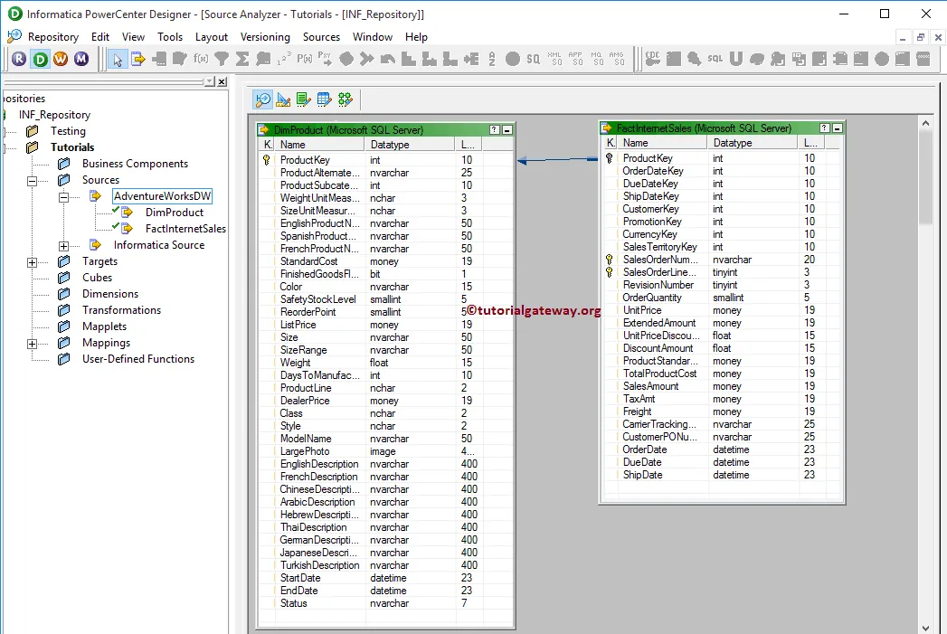
Please navigate to Target Designer and define the Target. In this Informatica Filter Transformation example, we are using the already created SQL table (Filter Transformation) as our target definition. Please refer Create Target table using Source Definition to understand the steps involved in creating a target definition

In order to create a new mapping for Informatica Filter Transformation, Please navigate to Mappings menu in Menu Bar and select the Create.. option. This will open the Mapping Name window as shown below. Here, you have to write a unique name for this mapping (m_Filter_Transformation) and click OK button.
TIP: Please refer Mapping article to understand the steps involved in creating Mapping.

Next, Drag and drop the [Dim Products] and [fact Internet Sales] source definitions from Sources folder to the mapping designer. Once you drag the source, PowerCenter Designer will automatically create the default transformation called source qualifier as we shown below.

As we all know that the [Dim Products] and [fact Internet Sales] tables have the Primary and Foreign key relationship. So, we removed one source qualifier and added the required fields from both tables to single source qualifier.

In order to create Filter transformation in Informatica, Please navigate to Transformation menu in Menu Bar and select the Create.. option as we shown below.

Once you click on the Create.. option, Create Transformation window will be opened as shown below. Please select the Filter Transformation from the drop-down list and specify the unique name (fil_SalesAmount) for it and click on Create button

Once you click on the Create button, filter transformation will be added to the mapping designer. In order to filter the records by an expression, filter Transformation requires some data. So, we have to connect the Source definition with the transformation using Autolink.. option (or select and Drag required fields).

Double click on the Filter transformation to provide the filter condition. From the below screenshot you can see the list of available properties in the Transformation tab:
- Select Transformation: By default, it will select the transformation you clicked on.
- Rename: This button will help you to rename the filter transformation to a more meaningful name.
- Make Reusable: If you check mark this option then, this transformation will become reusable transformation.
- Description: Please provide a valid description of this transformation.

Below screenshot will show you the list of available options in the Informatica Filter Transformation Ports tab:
- Port Name: List of available column names. By clicking the New column button you can add new columns and by clicking the scissors button you can delete the unwanted columns.
- I: Columns that are check-marked under this section are the filter transformation Input columns.
- O: Columns that are check-marked under this section are the filter transformation Output columns. If you unchecked any column then, that column will not be available to load in a target table.

The following screenshot will show you the list of available options in the Properties tab. By default Filter Condition will be set to TRUE and here only we have to provide the condition. In order to specify the condition, click on the Arrow button as shown below.
TIP: If you specify the Filter Condition to FALSE then filter condition will not allow single record.

Once you click on the arrow button, Expression Editor window will be opened as shown below. Here you can write custom expressions using the available functions, Ports (Column Names) and Variables.

For this example, we are using the simple expression i.e., SalesAmount > 2000. It means Informatica Filter transformation will return the records whose sales amount is greater than 2000

Once you finish configuring the properties, Click OK to close the transformation window.
Next, Drag and drop the target definition (Filter Transformation in Informatica) from the Targets folder to the mapping designer and connect the Transformation with the target definition. Please use the Autolink.. option to connect them.

Before we close the Mapping, Let us validate the mapping by going to Mapping Menu bar and selecting the Validate option.
Once we finish creating the Mapping we have to create the workflow for it. PowerCenter Workflow manager provides two approaches to create a workflow.
In this Informatica Filter Transformation example, we will create the Workflow manually. In order to create a new Workflow, Please navigate to Workflows Menu and select the Create option. This will open Create Workflow window as shown below. Please provide the unique name (wf_Filter_Transformation) and leave the default settings.

Once we created the workflow, our next step is to create a session task for our mapping.
NOTE: We strictly recommend to refer Workflow article to understand the steps involved in creating Workflow manually.
Creating a Session
There are two types of sessions:
For this Informatica Filter Transformation example, we are going to create Non-reusable Session. Please navigate to Tasks Menu and select the Create option to open the Create Task window. Here you have to select the Session as Task type (default) and enter a unique name (S_Filter_Transformation) for the session.
Once you click on the Create button, a new window called Mappings will be opened. Here you have to select the mapping you want to associate with this session. From the below screenshot you can observe that we are selecting the mapping (m_Filter_Transformation) that we created earlier (in Step 3).

Double click on the Session Task to configure it. Although we have to configure Sources, targets, and some common properties, we are explaining only a few properties. We strictly recommend visiting the Session article to understand the remaining properties.
From the below screenshot you can observe that we assigned the $target variable to Connection Value, we changed the Target Load Type option from Bulk to Normal mode and check marked the Truncate target table option to truncate the existing data from the destination table.

From the below screenshot you can observe that the Filter Transformation in Informatica workflow is a valid one. Now, Let us start the Workflow by navigating to Workflows menu and selecting the Start Workflow option.

Once you select the Start Workflow option, the PowerCenter Workflow monitor will be opened to monitor the workflow. From the below screenshot you can observe that our workflow is executed without any errors.

Let us open the SQL Server Management Studio to check whether we successfully restricted the records with Sales Amount less than 2000 using the Informatica Filter Transformation or not.

Java Transformation in Informatica
The Java Transformation in Informatica provides an opportunity to write a custom Java code within the transformation. If you are familiar with Java programming, then you can write a complex code inside this transformation.
For this Informatica Java Transformation example, we are going to use SP Source and Destination tables. From the below screenshot, you can see that the Source table has 15 records, and the Destination table is Empty.

In this example, we show how to create and configure Java Transformation in Informatica. Before we start configuring, First, let me connect with the Informatica repository service.
To do so, we have to provide the Admin Console credentials. So, Please provide the appropriate Username and Password you specified while installing the Server.
Once you connected successfully, Please navigate to Source Analyzer and define your Sources. In this Informatica Java Transformation example, we are using the SP Source table from the SQL Server database as our source definitions. Please refer to Database Source to understand the steps in creating a source definition

Please navigate to Target Designer to define the Target. In this Informatica Java Transformation example, we are using the existing SQL table (SP Destination) as our target definition. You can refer to Create Target table using Source Definition to understand the creation of a target definition

To create a new mapping for Informatica Java Transformation, Please navigate to the Mappings menu in Menu Bar. Next, select the Create.. option.

Once you select the Create.. option, a new Mapping Name window opens. Let me provide m_Java as the mapping name and click the OK button.

Drag and drop the SP Source from Sources folder to the mapping designer. Once you drag the source, Power Center Designer automatically creates the Source Qualifier Transformation (default transformation) for you.

To create Java transformation in Informatica, Please navigate to the Transformation menu in Menu Bar. Next, select the Create.. option.

Selecting the Create.. option opens the Create Transformation window. Please select the Java Transformation from the drop-down list and provide the unique name (Java_Employees) for this transformation and click on Create button

Clicking the Create button will pop up a new window called Active or Passive. Please select whether you want to use this Java Transformation as an Active transformation or passive Transformation.

By clicking OK will create a Java Transformation for you. Let me drag all the fields that are available in source definition to Java transformation.

Double click on the Informatica Java transformation to see and alter the properties. Below screenshot shows you the list of available properties in the Transformation tab:
- Select Transformation: By default, it selects the transformation you selected (or clicked on).
- Rename: This button helps you to rename the transformation name.
- Description: Use this place to provide a valid description.

The below screenshot shows you the list of available columns in the Ports tab. As you can, all the columns dragged from the source definition are in the OUTPUT section.
TIP: Few people may not drag fields from Source Qualifier at this point. They will create both Input and Output fields on their own, and then they point them to Source Qualifier.

To create new fields under the input section, select the INPUT, and then click the New field button.

In our Informatica Java Transformation source definition, we have 7 columns. So let me create 7 new fields under the INPUT section. We also need an extra output column for the New Income filed in our target table

Let me rename the Field names as per the Source Definition

Java Code Tab: This is used to write custom Java code. Here, the Left side window is a Navigator window – Which holds all Input, Output ports that are available in Java transformation, and few regularly used functions.

Let me write a simple code for this Informatica Java Transformation

Within the above code, we used the If Else Statement along with Equals method to check whether the Occupation of an employee is Management or not. If it is TRUE then we are adding 45750 to yearly income otherwise we added 25009. Code that we used is:
EmpID = in_EmpID;
FirstName = in_FirstName;
LastName = in_LastName;
Education = in_Education;
Occupation = in_Occupation;
YearlyIncome = in_YearlyIncome;
Sales = in_Sales;
if(in_Occupation.equals("Management"))
{
	NewIncome = in_YearlyIncome + 45750;
}
else
{
	NewIncome = in_YearlyIncome + 25009;
}
generateRow();
Once you finish configuring the Java Transformation, you have to map the Source qualifier with the Java Transformation Input fields.

Next, Drag and drop the target definition (SP Destination) from the Targets folder to the mapping designer. Next, connect the Output Fileds of a Java Transformation with the target definition using the Autolink.. option.

Before we close the Mapping, Let us Save, and Validate the mapping by going to Mapping Menu bar, and select the Validate option.
After you finish creating the Informatica Java Transformation Mapping, we have to create the workflow for it. PowerCenter Workflow Manager provides two approaches to create a workflow.
In this Informatica Java Transformation example, we will create the Workflow manually. To do so, Please navigate to Workflows Menu and select the Create option.

It opens a Create Workflow window. Please provide a unique name (wf_JavaEmp) and leave the default settings.

Once we created the workflow, our next step is to create a session task for our mapping.
There are two types of sessions:
For this Informatica Java Transformation example, we created a Non-reusable Session. To create Non-reusable Session, Please navigate to Tasks Menu and select the Create option as shown below.

Please provide a unique name (s_JavaEmp) for this session. Once you click on the Create button, a new window called Mappings will open. Here you have to select the mapping that you want to associate with this session, i.e., m_Java.

Double click on the Session task opens the Edit Tasks window. Within the mappings tab, we have to configure the Source, Target Connections.
First, let us configure the source connections by clicking on the SQ_SPSource source present in the Sources folder. Within the Connections, click on the Arrow button beside the Relational type, and select the Database Object (Database Name), i.e., Informatica Source

Now, we have to configure the Target Connection for this Informatica Java Transformation. So, click on the SPDestination present in the Targets folder. Within the Connections, click on the Arrow button beside the Relational type. Next, select the Database Object (Target Database Name), i.e., Informatica Target

Next, navigate to Workflows Menu and select the Validate option to validate the Workflow.

Now, Let me start the Informatica Java Transformation Workflow. To do so, navigate to the Workflows menu and select the Start Workflow option.

Let us open the SQL Server Management Studio and write following SQL Query.

Joiner Transformation in Informatica
The Joiner Transformation in Informatica is used to perform SQL Joins. There are four types of Joins in Informatica, and they Inner Join (Normal Join), Master Outer Join, Detail Outer Join and Full Outer Join. Joiner Transformation in Informatica is very useful to load data into the Dimension tables in Data Warehouse.
Normal Join: The Normal Join in Informatica is exactly similar to SQL Inner Join. It returns the records (or rows) present in both tables If there is at least one match between columns. Let us see the visual representation of the Normal Join for better understanding.

In this article, we are going to perform Normal Join on two SQL tables using Joiner Transformation in Informatica. Before we start designing the Mapping let us look at our two source tables on which we are going to perform Normal Join using Informatica Joiner Transformation.
Employees Table inside the Database is:

Department Table inside the

Before we start doing anything, First connect to Informatica repository service. In order to connect with Repository service we have to provide the Admin Console credentials so, Please provide the appropriate Username and Password and click on Connect button as shown below.
TIP: Here you have to provide the Admin Username and password that you specified while installing the Server.

Once you connected successfully, Please navigate to Source Analyzer and define your Sources. In this Informatica Joiner Transformation example, we are using Department and Employee tables from the SQL Server database as our source definitions. Please refer to Database Source to understand the steps involved in creating a source definition

Please navigate to Target Designer and define the Target. In this example, we are using the already created SQL table (Joiner Transformation in Informatica) as our target definition. Please refer Create Target table using Source Definition to understand the steps involved in creating a target definition

In order to create a new mapping, Please navigate to Mappings menu in Menu Bar and select the Create.. option. This will open the Mapping Name window as shown below. Here, you have to write a unique name for this mapping (m_Joiner_transformation) and click OK button.
TIP: Please refer Mapping article to understand the steps involved in creating Mapping.

Next, Drag and drop the Employee and Department source definitions from Sources folder to the mapping designer. Once you drag the source, PowerCenter Designer will automatically create the default transformation called source qualifier.
In order to create Joiner transformation in Informatica, Please navigate to Transformation menu in Menu Bar and select the Create.. option as we shown below.

Once you click on the Create.. option, Create Transformation window will be opened as shown below. Please click on the arrow to select the required one from drop-down list. Let us select the Informatica Joiner transformation

Next, Please specify the unique name for this Informatica Joiner Transformation (JNR_NORMAL) and click on Create button

Once you click on the Create button, the Informatica Joiner transformation will be added to the mapping designer. In order to perform Normal Join, the Joiner Transformation requires some data. So, we have to connect the Source definition with the transformation using Autolink.. option (or select and Drag required fields).

Double click on the Informatica Joiner transformation to configure the Join conditions. From the below screenshot you can see the list of available properties in the Transformation tab:
- Select Transformation: By default, it will select the transformation you clicked on.
- Rename: This button will help you to rename it to a more meaningful name.
- Make Reusable: If you check mark this option then, it will become reusable transformation.
- Description: Please provide a valid description.

The list of available options in the Informatica Joiner Transformation Ports tab:
- Port Name: List of available column names. By clicking the New column button you can add new columns and by clicking the scissors button you can delete the unwanted columns.
- I: Columns that are check-marked under this section are the Input columns.
- O: Columns that are check-marked under this section are the Joiner transformation Output columns. If you unchecked any column then, that column will not be available to load in a target table.
- M: Please checkmark the Column(s) that you want to use as Master table. It is always good practice to select the table holding the least records as Master table. Here, we are selecting a Department table as our Master table.
NOTE: You don’t have to select each and every column present in the Master table. If you select One column from Employee then it will automatically the remaining columns.

Below screenshot will show you the list of available options in the Informatica Joiner Transformation Properties tab:
- Join Type: In this example, we are performing Normal Join so, we are selecting the Normal Join from the drop-down list.
- Sorted Input: If we are using the sorted data then check mark this option.

Within the Condition tab, we have to specify the condition. In this example, we are going to perform Normal Join on Department and Employee table based on the condition Department. id = Employee.Depart Id. So, click on the New button (beside scissors) to create a new condition and select the columns names from Master and detail list

Once you finish configuring the Informatica Joiner Transformation properties, Click OK to close the window.
Next, Drag and drop the target definition from Targets folder to the mapping designer and connect the Joiner Transformation with the target definition. Please use the Autolink.. option to connect them.

Before we close the Mapping, Let us validate the Informatica Joiner Transformation mapping by going to Mapping Menu bar and selecting the Validate option.
Step 4: Creating a Workflow
Once we finish creating the Mapping we have to create the workflow for it. PowerCenter Workflow manager provides two approaches to create a workflow.
In this Informatica Joiner Transformation example, we will create the Workflow manually. In order to create a new Workflow, Please navigate to Workflows Menu and select the Create option. This will open Create Workflow window as shown below. Please provide the unique name (wf_joiner_transformation) and leave the default settings.

Once we created the workflow, our next step is to create a session for joiner transformation in informatica.
NOTE: We strictly recommend to refer Workflow article to understand the steps involved in creating Workflow manually.
Step 4(a): Creating Session
There are two types of sessions:
- Non-reusable Session Task: Please refer Session article to understand the steps involved in it.
- Reusable Session Task: Please refer Reusable Session article to understand the steps involved in it.
For this Informatica Joiner Transformation example, we are going to create Non-reusable Session. In order to create Non-reusable Session, Please navigate to Tasks Menu and select the Create option to open the Create Task window. Here you have to select the Session as Task type (default) and enter a unique name for the session.
Once you click on the Create button, a new window called Mappings will be opened. Here you have to select the mapping you want to associate with this session. From the below screenshot you can observe that we are selecting the mapping that we created earlier (in Step 3).

Double click on the Session Task to configure it. Although we have to configure some common properties, we are explaining only Sources, and targets properties. We strictly recommend visiting the Session article to understand the remaining properties.
Employee Source
Within the Connections, select the Arrow button beside the relational type to open the Relational Connection Browser as shown below. Here, Our Employee table is coming from the Source, we are using the Connection variable that we created in our previous step i.e., $Source

Department Source
Within the Connections, select the Arrow button beside the relational type to open the Relational Connection Browser as shown below. Here, Our Department table is also coming from the Source so we are using the Connection variable that we created in our previous step i.e., $Source

From the below screenshot you can observe that we assigned the $target variable to Connection Value, we changed the Target Load Type option from Bulk to Normal mode and check marked the Truncate target table option to truncate the existing data from the destination table.

From the below screenshot you can observe that the Informatica Joiner Transformation workflow is a valid one. Now, let us start the Workflow by navigating to the Workflows menu and selecting the Start Workflow option.

Once you select the Start Workflow option, the PowerCenter Workflow monitor will be opened to monitor the workflow. From the below screenshot you can observe that our Informatica Joiner Transformation workflow is executed without any errors.

Let us open the SQL Server Management Studio to check whether we successfully performed the Normal Join using the Joiner Transformation in Informatica.

Master Outer Join in Informatica
The Master Outer Join in Informatica is used to return all the existing records from Details table and only matching records from Master table.
Let us see the visual representation of the Master Outer Join in Informatica for better understanding.

In this article, we are going to perform Informatica Master Outer Join on two SQL tables using Joiner Transformation in Informatica.
Before we start designing the Mapping let us look at our two source tables on which we are going to perform Master Outer Join in Informatica.
Employees Table inside the Database is:

Department Table inside the

Before we start doing anything, First connect to the repository service with your Admin Console credentials.
TIP: Please refer to Normal Join, Detail Outer Join, and Full Outer Join articles to understand the remaining Joins in Informatica.
Once you have connected successfully, Please navigate to Source Analyzer and define your Sources. In this Informatica Master Outer Join transformation example, we use Department and Employee tables from the SQL Server database as our source definitions. Please refer to Database Source to understand the steps involved in creating a source definition

Please navigate to Target Designer and define the Target. In this example, we are using the already created SQL table (Master Outer Join in Informatica) as our target definition. Please refer Create Target table using Source Definition to understand the steps involved in creating a target definition

In order to create a new mapping, Please navigate to Mappings menu in Menu Bar and select the Create.. option. This will open the Mapping Name window as shown below. For this Informatica Master Outer Join transformation, you have to write a unique name for this mapping (m_Master_Outer) and click OK button.
TIP: Please refer Mapping article to understand the steps involved in creating Mapping.

Next, Drag and drop the Employee and Department source definitions from Sources folder to the mapping designer. Once you drag the source, PowerCenter Designer will automatically create the default transformation called source qualifier.
In order to create Joiner transformation in Informatica, Please navigate to Transformation menu in Menu Bar and select the Create.. option as we shown below.

Once you click on the Create.. option, Create Transformation window will be opened as shown below. Please select the Joiner transformation from a drop-down list and specify the unique name for this transformation (JNR_MASTER) and click on Create button

Once you click on the Create button, the Joiner transformation will be added to the mapping designer. In order to perform Master Outer Join, Joiner Transformation requires some data.
So, we have to connect the Source definition with the transformation using the Autolink.. option (or select and Drag required fields).

Double click on the Joiner transformation to configure the join conditions. From the below screenshot you can see the list of available options in the Ports tab:
- M: Please checkmark the Column(s) that you want to use as Master table. It is always good practice to select the table holding the least records as Master table. Here, we are selecting a Department table as our Master table.
NOTE: You don’t have to select each and every column present in the Master table. If you select One column from Employee then it will automatically the remaining columns.

The list of available options in the Master Outer Join transformation Properties tab:
- Join Type: In this example, we are performing Master Outer Join. So, we are selecting the Informatica Master Outer Join from the drop-down list.
- Sorted Input: If we are using the sorted data then check mark this option.

Within the Condition tab, we have to specify the condition. In this example, we are going to perform Informatica Master Outer Join on Department and Employee table based on the condition Department. id = Employee.Depart Id. So, click on the New button (beside scissors) to create a new condition and select the columns names from Master and detail list

Once you finish configuring the Joiner transformation properties, Click OK to close the transformation window.
Next, Drag and drop the target definition from Targets folder to the mapping designer and connect the Joiner Transformation with the target definition. Please use the Autolink.. option to connect them.

Before we close the Mapping, Let us validate the mapping by going to Mapping Menu bar and selecting the Validate option.
Step 4: Creating a Workflow
Once we finish creating the Mapping we have to create the workflow for Informatica master outer join. PowerCenter Workflow manager provides two approaches to create a workflow.
In this Master Outer Join example, we will create the Workflow manually. In order to create a new Workflow, Please navigate to Workflows Menu and select the Create option. This will open Create Workflow window as shown below.
Please provide the unique name (wf_Master_Outer) for this Informatica Master Outer Join transformation workflow and leave the default settings.

Once we created the Informatica master outer join workflow, our next step is to create a session.
NOTE: We strictly recommend to refer Workflow article to understand the steps involved in creating Workflow manually.
There are two types of sessions:
For this Informatica Master Outer Join example, we are going to create Non-reusable Session. Please navigate to Tasks Menu and select the Create option to open the Create Task window. Here you have to select the Session as Task type (default) and enter a unique name (S_Master_Outer) for the session.
Once you click on the Create button, a new window called Mappings will be opened. Here you have to select the mapping you want to associate with this session. From the below screenshot you can observe that we are selecting the mapping (m_Master_Outer) that we created earlier (in Step 3).

Double click on the Session Task to configure it. Although we have to configure Sources, targets, and some common properties, we are explaining only a few properties. We strictly recommend visiting the Session article to understand the remaining properties.
We assigned the $target variable to Connection Value, we changed the Target Load Type option from Bulk to Normal mode and check marked the Truncate target table option to truncate the existing data from the destination table.

From the below screenshot you can observe that the Master Outer Join in Informatica workflow is a valid one. Now, let us start the Workflow by navigating to the Workflows menu and selecting the Start Workflow option.

Once you select the Start Workflow option, the PowerCenter Workflow monitor will be opened to monitor the workflow. From the below screenshot you can observe that our workflow is executed without any errors.

Let us open the SQL Server Management Studio to check whether we successfully performed the Master Outer Join in Informatica using the Joiner Transformation or not.

Detail Outer Join in Informatica
The Detail Outer Join in Informatica is used to return all the existing records from Master table and only matching records from Detail table.
Let us see the visual representation of the Detail Outer Join in Informatica for better understanding.

In this article, we are going to perform Informatica Informatica Detail Outer Join on two SQL tables using Joiner Transformation. Before we start designing the Mapping let us look at our two source tables on which we are going to perform Detail Outer Join in Informatica.
Employees Table inside the Database is:

Department Table inside the Database is:

Before we start doing anything, First connect to the repository service with your Admin Console credentials.
TIP: Please refer to Normal Join, Master Outer Join, and Full Outer Join articles to understand the remaining Joins in Informatica.
Once you connected successfully, Please navigate to Source Analyzer and define your Sources. In this Informatica detail outer join example, we are using Department and Employee tables from SQL Server database as our source definitions. Please refer Database Source to understand the steps involved in creating source definition

Please navigate to Target Designer and define the Target. In this example, we are using the already created SQL table (Detail Outer Join in Informatica) as our target definition. Please refer Create Target table using Source Definition to understand the steps involved in creating a target definition

For this Informatica detail outer join example, we created the m_Detail_Outer mapping. Please refer Mapping article to understand creating Mapping. Next, Drag and drop the Employee and Department source definitions from the Sources folder to the mapping designer. Once you drag the source, PowerCenter Designer will automatically create the default transformation called source qualifier.
In order to create Joiner transformation in Informatica, Please navigate to the Transformation menu in Menu Bar and select the Create.. option as shown below.

Once you click on the Create.. option, Create Transformation window will be opened as shown below. Please select the Joiner transformation from a drop-down list and specify the unique name (JNR_DETAIL) for this transformation and click on Create button

Once you click on the Create button, the Joiner transformation will be added to the mapping designer. In order to perform Detail Outer Join, Joiner Transformation requires some data so, we have to connect the Source definition with the transformation using Autolink.. option (or select and Drag required fields).

Double click on the Joiner transformation to configure the join conditions. From the below screenshot you can see the list of available options in the Ports tab:
- M: Please checkmark the Column(s) that you want to use as Master table. It is always good practice to select the table holding the least records as Master table. Here, we are selecting a Department table as our Master table.
NOTE: You don’t have to select each and every column present in the Master table. If you select One column from Employee then Informatica will automatically the remaining columns.

Below screenshot will show you the list of available options in the Properties tab:
- Join Type: In this example, we are performing Informatica Detail Outer Join. So, we are selecting the Detail Outer Join from the drop-down list.
- Sorted Input: If we are using the sorted data then check mark this option.

Within the Condition tab, we have to specify the condition. In this example, we are going to perform Informatica Detail Outer Join on Department and Employee table based on the condition Department. id = Employee.Depart Id. So, click on the New button (beside scissors) to create a new condition and select the columns names from Master and detail list

Once you finish configuring the Joiner Transformation properties, Click OK to close the transformation window.
Next, Drag and drop the target definition (Detail Outer Join in Informatica) from Targets folder to the mapping designer and connect the Joiner Transformation with the target definition. Please use the Autolink.. option to connect them.

Before we close the Mapping, Let us validate the mapping by going to Mapping Menu bar and selecting the Validate option.
Once we finish creating the Mapping we have to create the workflow for it. PowerCenter Workflow manager provides two approaches to create a workflow.
In this Informatica Detail Outer Join example, we will create the Workflow manually. In order to create a new Workflow, Please navigate to Workflows Menu and select the Create option. This will open Create Workflow window as shown below. Please provide the unique name (wf_Detail_Outer) and leave the default settings.

Once we created the workflow, our next step is to create a session task for our mapping.
NOTE: We strictly recommend to refer Workflow article to understand the steps involved in creating Workflow manually.
There are two types of sessions:
For this Informatica Detail Outer Join example, we are going to create Non-reusable Session. Please navigate to Tasks Menu and select the Create option to open the Create Task window. Here you have to select the Session as Task type (default) and enter a unique name (S_Detail_Outer) for the session.
Once you click on the Create button, a new window called Mappings will be opened. Here you have to select the mapping you want to associate with this session. From the below screenshot you can observe that we are selecting the mapping (m_Detail_Outer) that we created earlier (in Step 3).

Double click on the Session Task to configure it. Although we have to configure Sources, targets, and some common properties, we are explaining only a few properties. We strictly recommend visiting the Session article to understand the remaining properties.
From the below screenshot you can observe that we assigned the $target variable to Connection Value, we changed the Target Load Type option from Bulk to Normal mode and check marked the Truncate target table option to truncate the existing data from the destination table.

From the below screenshot you can observe that the Informatica Detail Outer Join workflow is a valid one. Now, Let us start the Workflow by navigating to Workflows menu and selecting the Start Workflow option.

Once you select the Start Workflow option, the PowerCenter Workflow monitor will be opened to monitor the workflow. From the below screenshot you can observe that our Informatica Detail Outer Join workflow is executed without any errors.

Let us open the SQL Server Management Studio to check whether we successfully performed the Detail Outer Join in Informatica using the Joiner Transformation or not.

Full Outer Join in Informatica
The Full Outer Join in Informatica is another option available in Joiner Transformation which is used to return all the existing records from Master table and Detail table.
Let us see the visual representation of the Full Outer Join in Informatica for better understanding.

In this article, we are going to perform Informatica Full Outer Join on two SQL tables using Joiner Transformation. Before we start designing the Mapping let us look at our two source tables on which we are going to perform Full Outer Join in Informatica.
Department Table inside the Database is:

Employees Table inside the Database is:

Before we start configuring Informatica Full Join, First connect to the repository service with your Admin Console credentials.
TIP: Please refer to Normal Join, Master Outer Join, and Detail Outer Join articles to understand the remaining Joins.
Once you connected successfully, Please navigate to Source Analyzer and define your Sources. In this Informatica Full outer join example, we are using Department and Employee tables from SQL Server database as our source definitions.
Please refer Database Source to understand the steps involved in creating source definition

Please navigate to Target Designer and define the Target. In this example, we are using the already created SQL table (Full Outer Join in Informatica) as our target definition. Please refer Create a Target table using Source Definition to understand the steps involved in creating a target definition

In order to create a new mapping, Please navigate to Mappings menu in Menu Bar and select the Create.. option. This will open the Mapping Name window as shown below. Here, you have to write a unique name for this mapping (m_Full_Outer) and click OK button.
TIP: Please refer Mapping article to understand the steps involved in creating Mapping.

Next, Drag and drop the Employee and Department source definitions from Sources folder to the mapping designer. Once you drag the source, PowerCenter Designer will automatically create the default transformation called source qualifier.
In order to create Joiner transformation in Informatica, Please navigate to Transformation menu in Menu Bar and select the Create.. option as we shown below.

Once you click on the Create.. option, Create Transformation window will be opened. Please select the Joiner transformation from a drop-down list and specify the unique name (JNR_FULL) for this transformation and click on Create button

Once you click on the Create button, the Joiner transformation will be added to the mapping designer. In order to perform Full Outer Join, Joiner Transformation requires some data. So, we have to connect the Source definition with the transformation using the Autolink.. option (or select and Drag required fields).

Double click on the Joiner transformation to configure the join conditions. From the below screenshot you can see the list of available options in the Ports tab:
- M: Please checkmark the Column(s) that you want to use as Master table. From the below screenshot you can observe that Joiner Transformation automatically selected the Employee table as Master table

It is always good practice to select the table holding the least records as Master table. That’s why we are selecting a Department table as our Master table.
NOTE: You don’t have to select each and every column present in the Master table. If you select One column from Employee then Informatica will automatically the remaining columns.

Below Informatica Full outer join screenshot will show you the list of available options in the Properties tab:
- Join Type: In this example, we are performing Full Outer Join so, we are selecting the Full Outer Join from the drop-down list.
- Sorted Input: If we are using the sorted data then check mark this option.

Within the Condition tab, we have to specify the condition. In this example, we are going to perform Full Outer Join on Department and Employee table based on the condition Department. id = Employee.Depart Id. So, click on the New button (beside scissors) to create a new condition and select the columns names from Master and detail list

Once you finish configuring the Joiner Transformation properties, Click OK to close the transformation window.
Next, Drag and drop the target definition (Full Outer Join in Informatica) from Targets folder to the mapping designer and connect the Joiner Transformation with the target definition. Please use the Autolink.. option to connect them.

Before we close the Mapping, Let us validate the mapping by going to Mapping Menu bar and selecting the Validate option.
Once we finish creating the Mapping we have to create the workflow for it. PowerCenter Workflow manager provides two approaches to create a workflow.
In this Informatica Full Outer Join example, we will create the Workflow manually. In order to create a new Workflow, Please navigate to Workflows Menu and select the Create option. This will open Create Workflow window as shown below. Please provide the unique name (wf_Full_Outer) and leave the default settings.

Once we created the workflow, our next step is to create a session task for our mapping.
NOTE: We strictly recommend to refer Workflow article to understand the steps involved in creating Workflow manually.
There are two types of sessions:
- Non-reusable Session Task: Please refer Session article to understand the steps involved in it.
- Reusable Session Task: Please refer to the Reusable Session article to understand the steps involved in it.
For this Informatica Full Outer Join example, we are going to create Non-reusable Session. Please navigate to Tasks Menu and select the Create option to open the Create Task window. Here you have to select the Session as Task type (default) and enter a unique name (S_Full_Outer) for the session.
Once you click on the Create button, a new window called Mappings will be opened. Here you have to select the mapping you want to associate with this session. From the below screenshot you can observe that, we are selecting the mapping (m_Full_Outer) that we created earlier (in Step 3).

Double click on the Session Task to configure it. Although we have to configure Sources, targets, and some common properties, we are explaining only a few properties. We strictly recommend visiting the Session article to understand the remaining properties.
From the below screenshot you can observe that we assigned the $target variable to Connection Value and check marked the Truncate target table option to truncate the existing data from the destination table.

From the below screenshot you can observe that the Full Outer Join in Informatica workflow is a valid one. Now, Let us start the Workflow by navigating to Workflows menu and selecting the Start Workflow option.

Once you select the Start Workflow option, the PowerCenter Workflow monitor will be opened to monitor the workflow. From the below screenshot you can observe that our Informatica Full Outer Join workflow is executed without any errors.

Let us open the SQL Server Management Studio to check whether we successfully performed the Full Outer Join in Informatica using the Joiner Transformation or not.

Lookup Transformation in Informatica
The Lookup Transformation in Informatica is very useful to look up data present in Flat Files, Relational tables and Views. In this article, we will show you, How to perform the lookup operation on the SQL server database table using the Lookup Transformation in Informatica with an example.
Before we start designing the Mapping let us look at our source table on which we are going to perform Informatica Lookup operation and the lookup table
Our Lookup table will be the table inside the Source Database is:

Our source table will be the below table inside the Database is:

In this Informatica Lookup Transformation example, our task is to compare the Country name present in the Source table with a Lookup table and
- If they match then we will load them in [Lookup Matched Rows] target table along with Country code present in the Lookup table
- If they don’t match then we will load them in [Lookup Unmatched Rows] target table
TIP: You can extend this functionality by performing some operations on Non-matching records and store them in a matched table using the Union Transformation.
Before we start configuring the Lookup Transformation in Informatica, First connect to the Informatica repository service. In order to connect with the Repository service we have to provide the Admin Console credentials so, Please provide the appropriate Username and Password and click on Connect button as shown below.
TIP: Here you have to provide the Admin Username and password that you specified while installing the Server.

Once you connected successfully, Please navigate to Source Analyzer and define your Sources.
In this Informatica Lookup Transformation example, we are using the table from the SQL Server database as our source definitions. Please refer to Database Source to understand the steps involved in creating a source definition

Please navigate to Target Designer and define the Target. In this Informatica Lookup Transformation example, we are using the already created SQL tables ([Lookup Matched Rows] and [Lookup Unmatched Rows]) as our target definitions. Please refer Create Target table using Source Definition to understand the steps involved in creating a target definition

In order to create a new mapping for Informatica Lookup Transformation, Please navigate to Mappings menu in Menu Bar and select the Create.. option. This will open the Mapping Name window as shown below.
Here, you have to write a unique name for this mapping (m_Lookup_Transformation) and click OK button.
TIP: Please refer Mapping article to understand the steps involved in creating Mapping

Next, Drag and drop the source definition from the Sources folder to the mapping designer. Once you drag the source, the PowerCenter designer will automatically create the default transformation called source qualifier.
In order to create Lookup Transformation in Informatica, Please navigate to Transformation menu in Menu Bar and select the Create.. option.

Once you click on the Create.. option, Create Transformation window will be opened as we shown below. Please select the Informatica Lookup Transformation from the drop-down list and specify the unique name (LKP_Country) for this transformation and click on Create button

Once you click on the Create.. button, a Select Lookup Table for Lookup Transformation window will be opened as shown below. Here, we want to import a relational table from SQL database so, click on Import and select From Relational Table.. option
TIP: If your lookup table is present in Source or Target then select it.

Once you select From Relational Table.. option, Import tables window will be opened. Here we are selecting our lookup table called [LookupTransformationSource]. Please refer Import Data from Relation Database article to understand the steps involved in it.

Once you click on the Create button, the Informatica Lookup Transformation will be added to the mapping designer. Double click on it to configure its settings.
The list of available options in the Ports tab. We added one new Input port (IN_CountryName) in this Informatica Lookup Transformation.

Within the Properties section, we change the Connection Information and assigned it with the $Source variable.

Within the condition tab we added one condition CountryName = IN_CountryName. Below condition states that it will check the lookup input source (i.e., Country Name) is equal to existing Country Name or Not, and if the condition is TRUE then it will return the corresponding Country Code.

Once you finish configuring the Informatica Lookup transformation, Please drag the Country Name field from the Source Qualifier to the IN_CountryName field in the lookup table
Please refer Router Transformation article to understand the steps involved in creating it. Once you created it, Please connect the Source qualifier with the router transformation by dragging the required fields.
From the below Informatica Lookup Transformation screenshot you can observe that we are adding all the columns from the Source Qualifier and Cid, Country Name from a Lookup table.

Double click on the Router transformation to add Groups. From the below screenshot, you can observe that we created one group for Non-Matching records and one default group.
Let us provide the expression or condition for the First group (Non-Matching) by clicking the arrow button as we shown below. This will open the Expression Editor to write a custom expression.
Here, we want the records whose Country Name is not present in the Lookup table. So, we are writing the below-shown expression (ISNULL(CountryName). It means all the Null values will be placed in Non Matched Group and Not null values will pass to Default Group.

Once you finish configuring the properties, Click OK to close the transformation window.

Next, Drag and drop the target definitions ([Lookup Matched Rows] and [Lookup Unmatched Rows]) from Targets folder to the mapping designer as shown below.
Next, Please connect the Informatica Lookup Transformation (Output Group 1) with the [Lookup Unmatched Rows] table and Default Group with Router [Lookup Matched Rows].
TIP: You can use the Autolink.. option to link those fields.

Before we close the Mapping, Let us validate the mapping by going to Mapping Menu bar and selecting the Validate option.
Once we finish creating the Mapping for Informatica Lookup Transformation, we have to create the workflow for it. PowerCenter Workflow manager provides two approaches to create a workflow.
In this Informatica Lookup Transformation example, we will create the Workflow manually. Once we created the workflow, our next step is to create a session task for our mapping.
There are two types of sessions:
- Non-reusable Session Task: Please refer Session article
- Reusable Session Task: Please refer to Reusable Session article
For this Informatica Lookup Transformation example, we are going to create Non-reusable Session. Please navigate to Tasks Menu and select the Create option to open the Create Task window. Here you have to select the Session as Task type (default) and enter a unique name (S_Lookup_Transformation) for the session.
Once you click on the Create button, a new window called Mappings will be opened. Here you have to select the mapping you want to associate with this session.
In this Informatica Lookup Transformation example, we are selecting the mapping (m_Lookup_Transformation) that we created earlier (in Step 3).

Double click on the Session Task to configure it. Although we have to configure Sources, targets, and some common properties, we are not going to explain them here. We strictly recommend visiting the Session article to understand the properties.
From the below screenshot you can observe that the lookup transformation in Informatica workflow is a valid one. Now, Let us start the Workflow by navigating to Workflows menu and selecting the Start Workflow option.

Once you select the Start Workflow option, the PowerCenter Workflow monitor will be opened to monitor the workflow. And our Informatica Lookup Transformation workflow is executed without any errors.

Let us open the SQL Server Management Studio to check whether we successfully stored the unmatched records or not.

Let us open the SQL Server Management Studio to check whether we successfully stored the matched records using the lookup transformation in Informatica or not.

Unconnected Lookup Transformation in Informatica
The Unconnected Lookup Transformation in Informatica is nothing but a programming function with parameter and in order to call this unconnected lookup, we have to use the Expression transformation.
In this article, we will show you, How to perform unconnected Lookup Transformation in Informatica with an example. Before we start designing the Mapping let us look at our source table on which we are going to perform Lookup operation and the Lookup table
Employees Table inside the Source Database is:
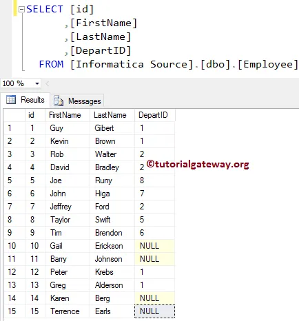
Our Lookup table will be the Department Table inside the Database:

In this Informatica unconnected lookup transformation example, our task is to load [First Name] and [Last Name] from the source (Employee table) table into the target table and also [Department Name] from the Department table. We can achieve the same using the Full Outer Join also but we will show you the alternative i.e unconnected Lookup Transformation in Informatica.
Before we start configuring the unconnected Lookup Transformation in Informatica, First connect to Informatica repository service.
In order to connect with the Repository service, we have to provide the Admin Console credentials. So, Please provide the appropriate Username and Password and click on Connect button as shown below.
TIP: Here you have to provide the Admin Username and password that you specified while installing the Server.

Once you connected successfully, Please navigate to Source Analyzer and define your Sources. In this Unconnected Lookup in Informatica example, we are using the Employee table from SQL Server database as our source definitions.
Please refer Database Source to understand the steps involved in creating source definition

Please navigate to Target Designer and define the Target. In this example, we are using the already created SQL table (Unconnected Lookup) as our target definition. Please refer Create Target table using Source Definition to understand the steps involved in creating a target definition

In order to create a new mapping, Please navigate to Mappings menu in Menu Bar and select the Create.. option. This will open the Mapping Name window as shown below. Here, you have to write a unique name for this mapping (m_Unconnected_Lookup) and click OK button.
TIP: Please refer Mapping article to understand the steps involved in creating Mapping.

Next, Drag and drop the [Employee] source definition from Sources folder to the mapping designer. Once you drag the source, the PowerCenter designer will automatically create the default transformation called source qualifier.
In order to create Lookup Transformation in Informatica, Please navigate to Transformation menu in Menu Bar and select the Create.. option as we shown below.

Once you click on the Create.. option, Create Transformation window will be opened as we shown below. Please select the Lookup Transformation from the drop-down list and specify the unique name (LKP_Department) for this transformation and click on Create button

Once you click on the Create.. button, a Select Lookup Table for Lookup Transformation window will be opened as shown below. Here, we are selecting the department table present in the Source

Once you click on the Create button, the Lookup Transformation will be added to the mapping designer. Since we are explaining about the unconnected lookup transformation there is no need to connect the transformation with the source qualifier.

The list of available options in the Informatica unconnected lookup transformation Ports tab. Here, we added one new Input port (IN_DeptID) and removed the id from the output port.

Within the condition tab, we added one condition id = IN_DeptID. Below condition states that whenever this lookup transformation is called they have to provide the parameter value of integer data type.
Once they pass the value, Lookup transformation will check whether the value is equal to id or not, and if the condition is TRUE then it will return the corresponding department name otherwise NULL will be returned.

Please refer Expression Transformation article to understand the steps involved in creating it. Once you created it, Please connect the Source qualifier with the expression transformation by dragging the required fields.
We are adding [First Name], [Last Name] and [DepartID] to the expression transformation. Double click on the Expression transformation to write the custom expressions.

From the below screenshot you can observe that we created New Output Column called Department name. We are going to use this column to store the department name we get from the Informatica unconnected lookup transformation.
Click on the arrow button beside the Mapping Name as we shown below to write the custom expression

This will open the Expression Editor to write a custom expression. Here, we want to get the Department Name from the Lookup Transformation.
To do this, Go to the Functions tab and search for Lookups folder and select the Lookup that we created earlier. As we all know that, we assigned the condition in Lookup transformation. It means we have to provide the parameter value of type integer.
TIP: Lookup transformation will check the condition id = DepartID and if the condition is TRUE then it will return the corresponding department name otherwise NULL will be returned.

Once you finish writing the expressions, Click OK to close the transformation window. Next, Drag and drop the target definition (Unconnected Lookup) from Targets folder to the mapping designer and connect the expression transformation with the target definition. Please use the Autolink.. option to connect them.

Before we close the Mapping, Let us validate the Informatica unconnected lookup mapping by going to Mapping Menu bar and selecting the Validate option.
Once we finish creating the Mapping we have to create the workflow for it. PowerCenter Workflow manager provides two approaches to create a workflow.
In this Informatica Unconnected Lookup Transformation example, we will create the Workflow manually. Once we created the workflow, our next step is to create a session task for our mapping.
There are two types of sessions:
For this Unconnected Lookup in Informatica example, we are going to create Non-reusable Session. Please navigate to Tasks Menu and select the Create option to open the Create Task window. Here you have to select the Session as Task type (default) and enter a unique name (S_Unconnected_Lookup) for the session.
Once you click on the Create button, a new window called Mappings will open. Here you have to select the mapping you want to associate with this session. In this Informatica unconnected lookup transformation, we are selecting the mapping (m_Unconnected_Lookup) that we created earlier (in Step 3).

Double click on the Session Task to configure it. Although we have to configure Sources, targets, and some common properties, we are not going to explain them here. We strictly recommend visiting the Session article to understand the properties.
The unconnected lookup transformation in informatica workflow is a valid one. Now, Let us start the Workflow by navigating to Workflows menu and selecting the Start Workflow option.

Once you select the Start Workflow option, the PowerCenter Workflow monitor will open to monitor the workflow. And our Informatica Unconnected Lookup workflow was executed without any errors.

Let us open the SQL Server Management Studio to check whether we successfully stored the stored the information from both Source and lookup table using the unconnected lookup transformation in informatica or not.

Normalizer Transformation in Informatica
The Normalizer Transformation in Informatica is an Active, and Connected transformation. This Informatica Normalizer transformation is used to normalize the denormalized data. Or you can simply say, divide single in a table to multiple rows.
For this Informatica Normalizer transformation example, we are going to use the below show data (Denormalized Source table)

And the destination tables are:

Before we start configuring the Informatica Normalizer Transformation, First let me connect with the repository service. To do so, enter the Admin Console username and password you specified while installing the Server.
Once you connected successfully, Please navigate to Source Analyzer and define your Sources. In this example, we are using the Denormalized Source table from the SQL Server database as our source definitions. Please refer Database Source article

Please navigate to Target Designer and define the Target. In this Informatica Normalizer Transformation example, we are using the already created SQL tables (Normalized prosecutors and Sales) as our target definition. Please refer Target table using Source Definition to understand the target definition

To create a new mapping for Informatica Normalizer Transformation, Please navigate to Mappings menu in Menu Bar, and select the Create.. option.

It opens the Mapping Name window to write a unique name (m_normalizer) for this mapping. Next, click the OK button.

Drag and drop the DenormalizedSource source definitions from Sources folder to the mapping designer. Once you drag the source, the Power Center designer automatically creates the Source Qualifier for you.
Next, let me create a Normalizer Transformation in Informatica. To do so, Please navigate to the Transformation menu and select the Create.. option

It opens the Create Transformation window. Please choose the normalizer transformation and provide the unique name (nrm_ProductSale) and then click on Create button

Now you can see the Informatica Normalizer Transformation in your mapping area. Remember, you can’t simply drag and drop fields from Source Qualifier to Normalizer. So, we have to create the fields inside it explicitly.

Double click on the Informatica Normalizer transformation to edit the Transformation. Next, go to the Normalizer tab, and use the New Field option to add new fields.

From the below screenshot, you can observe that We added 7 new columns using the New Port button. Remember, both the Data type and Precision should match with the input and output fields.

Next, we selected the Year column and clicked the Right Shift button beside the Level.

It creates a Level field, and shift the Year column to Level 2.

Similarly, we added the Sales and Orders columns to Level 2. In our Source table Year, Orders, and Sales are repeating for 4 times (2014, 2015, 2016, and 2017). That’s why we assigned 4 to Occurs. If this is not the case, then use an appropriate number.

Now you can see the Number of Input and Output ports that are automatically created by the Normalizer Transformation in Informatica.

You can see the Informatica Normalizer Transformation will all the required Filed name. Now we have to connect the Input and Outputs to this.

First, we connected the Source Qualifier with the Informatica Normalizer Transformation

Next, Drag and drop the target definition from the Targets folder to the mapping designer

Connect the Output fields from Normalizer transformation to the target definitions using the Autolink.. option. Before we close the Informatica Normalizer transformation Mapping, Let us validate the mapping by going to Mapping and selecting the Validate option.

After we finish creating the Mapping, we have to create a workflow for it. Power Center Workflow manager provides two approaches to create a workflow.
In this Informatica Normalizer transformation example, we will create the Workflow manually. To do so, Please navigate to Workflows Menu and select the Create option.

It opens the Create Workflow window to provide the unique name (wf_NormalizerTrans) and leave the default settings.

Once we created the workflow for Informatica Normalizer Transformation, our next step is to create a session task for our mapping.
There are two types of sessions:
For this Informatica Normalizer transformation example, we will create a Non-reusable Session. To create, Please navigate to Tasks Menu and select the Create option.

Please provide a unique name for this Informatica Normalizer transformation session. Here, we are naming it as s_NormalizerTran. Once you click on the Create button, a new window called Mappings will open. Here, we are selecting the m_normalizer

Please link the Start Task and the session task.

Double click on the Session task will open the Edit Tasks window. Within Properties Tab
$Source connection value: This property will store the relational source information in the $Source variable. So, click on the Arrow we marked below, and select the SQL Tutorial as the source information.

$Target connection value: This property will store the relational target information in the $Target variable. So, click on the Arrow we marked below, and select the SQL Test target as the Target information.

Within the mappings tab, we have to configure the Source, target Connections. First, let us configure the source connections by clicking on the SQ_DenormalizedSource source present in the Sources folder.
Within the Connections, click on the Arrow button beside the Relational type, and use the Connection variable that we created before, i.e., $Source

Now, we have to configure the Target Connection. So, click on the NormalizedProducts present in the Targets folder.
Within the Connections, click on the Arrow button beside the Relational type, and use the Connection variable $Target

Do the same for the NormalizedSales Target

Next, navigate to Workflows Menu and select the Validate option to validate the Workflow.

Now, Let me start the Informatica Normalizer Transformation Workflow. To do so, navigate to the Workflows menu and select the Start Workflow option.
Once you select the Start Workflow option, the PowerCenter Workflow monitor opened to monitor the workflow.
Let us open the SQL Server Management Studio to check whether we successfully Normalized the data or not. First, look at the products table:

Let me show you the sales.

Rank Transformation in Informatica
Rank Transformation in Informatica is similar to SQL RANK function, which is used to select the Top or bottom rank of data. In real-time, this transformation will be very helpful.
For example, you can use this Informatica rank transformation to select the top 10 regions with the highest and lowest sales Or bottom (underperforming) 20 products or regions etc.
For this Informatica rank transformation example, we are going to use the below show data
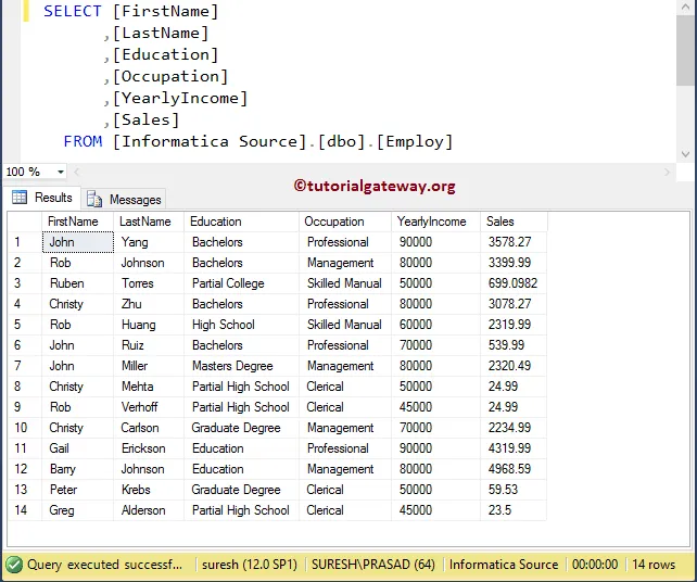
Before we start configuring the rank transformation in Informatica, First connect to the repository service.
In order to connect with the Informatica Repository service, we have to provide the Admin Console Username and Password you specified while installing the Server. Next, click on Connect button.

Once you connected successfully, Please navigate to Source Analyzer and define your Sources. In this Informatica rank transformation example, we are using the [Employ] table from the SQL Server database as our source definitions. Please refer to Database Source to understand the steps involved in creating a source definition

Please navigate to Target Designer and define the Target. In this example, we are using the already created SQL table as our target definition. Please refer Create Target table using Source Definition to understand creating a target definition

In order to create a new mapping for rank transformation in informatica, Please navigate to Mappings menu in Menu Bar and select the Create.. option. This will open the Mapping Name window as shown below. Here, you have to write a unique name for this mapping (m_Rank_Transformation) and click OK button.

Next, Drag and drop the [Employ] source definition from Sources folder to the mapping designer. Once you drag the source, the PowerCenter designer will automatically create the default transformation called source qualifier.
In order to create Rank transformation in Informatica, Please navigate to Transformation menu and select the Create.. option as we shown below.

Once you click on the Create.. option, Create Transformation window will be opened as shown below. Please select the Informatica Rank Transformation from the drop-down list and specify the unique name (rnk_Income) for this transformation and click on Create button

Once you click on the Create button, the Informatica rank transformation will be added to the mapping designer.
To rank the data, it requires some data. So, we have to connect the Source definition with the transformation by dragging the required fields.

From the above screenshot, you can observe the new item called RANKINDEX and this is default port created by the Informatica rank transformation. This output port will hold the ranking number so, we have to assign this output port to target table rank column.
Double click on the Informatica Rank transformation to provide the ranking factor (based on which column you want to rank). From the below screenshot you can see the list of available properties in the Transformation tab:
- Select Transformation: By default, it will select the transformation you clicked on.
- Rename: This button will help you to rename to a more meaningful name.
- Make Reusable: If you check mark this option then, this transformation will become reusable transformation.
- Description: Please provide a valid description.

Below screenshot will show you the list of available options in the Informatica Rank Transformation Ports tab:
- Port Name: List of available column names. By clicking the New column button you can add new columns and by clicking the scissors button you can delete the unwanted columns.
- I: Columns that are check-marked under this section are the Input columns.
- O: Columns that are check-marked under this section are the Output columns. If you unchecked any column then, that column will not be available to load in a target table.
- R: Please checkmark the Column that you want to use as ranking factor (based on which column you want to rank). For example, If you want to rank the data by yearly Income then you have to checkmark it as we shown below.

Below screenshot show you the list of available options in the Informatica Rank Transformation Properties tab.
- Cache Directory: Integration service will store the Cache files in this location.
- Top/Bottom: This will provide two options for the user i.e, Top and Bottom. If you want to rank the data from top to bottom (Z to A) then use the Top option or, for the bottom to top (A to Z) then use Bottom option.
- Number of Ranks: Please enter the number of rows you want to rank for. By default, the value will be 1 and it means, the Informatica rank transformation will select only 1 record.
- Case Sensitive String Comparison: If you check mark this option then, While sorting the data transformation will perform Case Sensitive String Comparison
For this example, we want to rank every record present in Employ table based on their Yearly Income (in descending order) that’s why we selected Top/Bottom property value as Top as and the Number of Ranks property value as 20 (our maximum records are 14)

Once you finish configuring the properties, Click OK to close the transformation window.
Next, Drag and drop the target definition (Rank Transformation) from Targets folder to the mapping designer and connect the Transformation with the target definition. Please use the Autolink.. option to connect them.

Before we close the Mapping, Let us validate the mapping by going to Mapping Menu bar and selecting the Validate option.
Once we finish creating the Mapping we have to create the workflow for it. PowerCenter Workflow manager provides two approaches to create a workflow.
In this Informatica Rank Transformation example, we will create the Workflow manually. To create a new Workflow, Please navigate to Workflows Menu and select the Create option. This will open Create Workflow window. Please provide the unique name (wf_Rank_Transformation) and leave the default settings.

Once we created the workflow, our next step is to create a session task for our Rank Transformation mapping.
There are two types of sessions:
For this Informatica Rank Transformation example, we are going to create Non-reusable Session. Please navigate to Tasks Menu and select the Create option to open the Create Task window. Here you have to select the Session as Task type (default) and enter a unique name (S_Rank_Transformation) for the session.
Once you click on the Create button, a new window called Mappings will be opened. Here you have to select the mapping you want to associate with this session.
From the below screenshot you can observe that we are selecting the mapping (m_Rank_Transformation) that we created earlier (in Step 3).

Double click on the Session Task to configure it. Although we have to configure Sources, targets, and some common properties, we are explaining only a few properties. We strictly recommend visiting the Session article to understand the remaining properties.
From the below screenshot you can observe that we assigned the $target variable to Connection Value, we changed the Target Load Type option from Bulk to Normal mode and check marked the Truncate target table option to truncate the existing data from the destination table.

From the below screenshot you can observe that the Rank Transformation in Informatica workflow is a valid one. Now, let us start the Workflow by navigating to the Workflows menu and selecting the Start Workflow option.

Once you select the Start Workflow option, the PowerCenter Workflow monitor will be opened to monitor the workflow. From the below screenshot you can observe that our Informatica Rank Transformation workflow is executed without any errors.

Let us open the SQL Server Management Studio to check whether we successfully ranked the records using Yearly Income using the Informatica Rank Transformation or not.

We can achieve the above output using the following SQL Query:
SELECT [FirstName]
      ,[LastName]
      ,[Education]
      ,[Occupation]
      ,[YearlyIncome]
      ,[Sales]
      ,RANK() OVER (
                     ORDER BY [YearlyIncome] DESC
          	   ) AS RANK
  FROM [Customers]
Let us change the Top/Bottom property to Bottom and refresh the mapping. It means Informatica rank transformation workflow will rank the Employ table based on the Yearly Income in Ascending order (0 as 1, 1 as 2 …. )

Let us open the SQL Server to check whether we successfully ranked the records using Yearly Income (in ascending order) or not. Please refer to Functions article.

Informatica Rank Transformation with Group By
The Informatica Rank Transformation is similar to SQL RANK function, which is used to select the Top or bottom rank of data. In this article, we are going to explain the steps involved in configuring the Informatica Rank Transformation with Group By along with an example.
For this example, we are going to use the below show data.
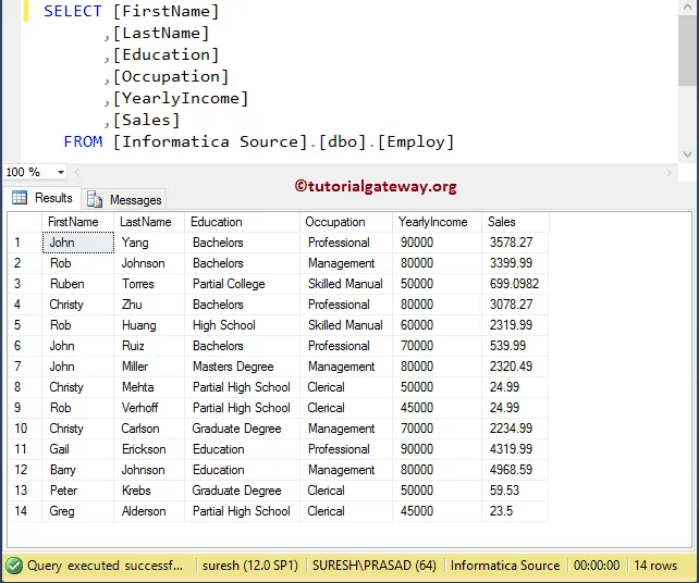
Before we start configuring the rank transformation, First connect to the Informatica repository service. In order to connect with the Repository service, we have to provide the Admin Console credentials. So, Please provide the appropriate Username and Password that you specified while installing the Server and click on Connect button as shown below.

TIP: Please refer Rank Transformation in Informatica article to understand the transformation without Grouping
Step 1: Creating Source Definition
Once you connected successfully, Please navigate to Source Analyzer and define your Sources. In this example, we are using [Employ] table from SQL Server database as our source definitions. Please refer to Database Source to understand the steps involved in creating a source definition

Step 2: Creating a Target Definition
Please navigate to Target Designer and define the Target. In this example, we are using the already created SQL table as our target definition. Please refer Create Target table using Source Definition to understand the steps involved in creating a target definition

Step 3: Creating Mapping
In order to create new mapping, Please navigate to Mappings menu in Menu Bar and select the Create.. option. This will open the Mapping Name window as shown below. Here, you have to write a unique name for this mapping (m_Rank_Transformation) and click OK button.
TIP: Please refer Mapping article to understand the steps involved in creating Mapping.

Next, Drag and drop the [Employ] source definition from Sources folder to the mapping designer. Once you drag the source, the PowerCenter designer will automatically create the default transformation called source qualifier.
In order to create Rank transformation in Informatica with the group by, Please navigate to the Transformation menu in Menu Bar and select the Create.. option as shown below.

Once you click on the Create.. option, Create Transformation window will be opened as shown below. Please select the Rank Transformation from drop down list and specify the unique name (rnk_Income) for this transformation and click on Create button

Once you click on the Create button, the rank transformation will be added to the mapping designer. In order to rank the data, rank Transformation requires some data. So, we have to connect the Source definition with the transformation by dragging the required fields.

From the above screenshot you an observe the new item called RANKINDEX and this is default port created by the Rank Transformation. This output port will hold the ranking number so, we have to assign this output port to target table rank column.
Double click on the Rank transformation to provide the ranking factor (based on which column you want to rank). Below screenshot will show you the list of available options in the Ports tab:
- R: Please checkmark the Column that you want to use as ranking factor (based on which column you want to rank). For example, If you want to rank the data by yearly Income then you have to checkmark it as we shown below.
- Group By: Please checkmark the Column that you want to use for Group by. In this example, we want to group the Employ table using the Occupation and then we want to rank employees inside the individual group.

Below screenshot will show you the list of available options in the Properties tab.
- Top/Bottom: This will provide two options for the user i.e, Top and Bottom. If you want to rank the data from top to bottom (Z to A) then use the Top option or, if rank the data from bottom to top (A to Z) then use Bottom option.
- Number of Ranks: Please enter the number of rows you want to rank for. By default, the value will be 1 and it means, the rank transformation will select only 1 record.
For this example, we want to rank every record present in Employ table based on their Yearly Income (in descending order). That’s why we selected Top/Bottom property value as Top as and the Number of Ranks property value as 20 (our maximum records are 14)

Once you finish configuring the properties, Click OK to close the transformation window.
Next, Drag and drop the target definition (Rank Transformation) from Targets folder to the mapping designer and connect the Transformation with the target definition. Please use the Autolink.. option to connect them.

Before we close the Mapping, Let us validate the mapping by going to Mapping Menu bar and selecting the Validate option.
Step 4: Creating a Workflow
Once we finish creating the Mapping we have to create the workflow for it. PowerCenter Workflow manager provides two approaches to create a workflow.
In this example, we will create the Workflow manually. In order to create a new Workflow, Please navigate to Workflows Menu and select the Create option. This will open Create Workflow window as shown below. Please provide the unique name (wf_Rank_Transformation) and leave the default settings.

Once we created the workflow, our next step is to create a session task for our mapping.
NOTE: We strictly recommend to refer Workflow article to understand the steps involved in creating Workflow manually.
Step 4(a): Creating Session
There are two types of sessions:
- Non-reusable Session Task: Please refer Session article to understand the steps involved init.
- Reusable Session Task: Please refer Reusable Session article to understand the steps involved init.
For this example, we are going to create Non-reusable Session. Please navigate to Tasks Menu and select the Create option to open the Create Task window. Here you have to select the Session as Task type (default) and enter a unique name (S_Rank_Transformation) for the session.
Once you click on the Create button, a new window called Mappings will be opened. Here you have to select the mapping you want to associate with this session. From the below screenshot you can observe that, we are selecting the mapping (m_Rank_Transformation) that we created earlier (in Step 3).

Double click on the Session Task to configure it. Although we have to configure Sources, targets, and some common properties, we are explaining only a few properties. We strictly recommend visiting the Session article to understand the remaining properties.
From the below screenshot you can observe that, we assigned the $target variable to Connection Value, we changed the Target Load Type option from Bulk to Normal mode and check marked the Truncate target table option to truncate the existing data from the destination table.

From the below screenshot you can observe that the Informatica Rank Transformation with the group by workflow is a valid one. Now, let us start the Workflow by navigating to the Workflows menu and selecting the Start Workflow option.

Once you select the Start Workflow option, the PowerCenter Workflow monitor will be opened to monitor the workflow. From the below screenshot you can observe that our workflow is executed without any errors.

Let us open the SQL Server Management Studio to check whether we successfully ranked the records using Yearly Income using the Informatica Rank Transformation with a group by or not.

We can achieve the above output using the following SQL RANK Function Query:
SELECT [FirstName]
      ,[LastName]
      ,[Education]
      ,[Occupation]
      ,[YearlyIncome]
      ,[Sales]
      ,RANK() OVER (
                     PARTITION BY Occupation
                     ORDER BY [YearlyIncome] DESC
          	   ) AS RANK
  FROM [Customers]
Router Transformation in Informatica
The Router Transformation in Informatica is just like IF condition or CASE statement. It will check the given condition and based on the condition result, an output will be sent to the appropriate destination path. This is similar to Filter transformation and we can use the Informatica Router Transformation when we have to test multiple conditions.
The Router Transformation in Informatica is very useful in real-time. For example, if we have a situation where we want to store the Employees records whose salary is greater than 40000 in one Table and less than 40000 in another table then we can use this Informatica Router Transformation to split the data based on the specified expression.
For this Informatica Router Transformation example, we are going to use the below show data. Here, Our task is to conditionally split the below-shown data and store them in multiple database tables.
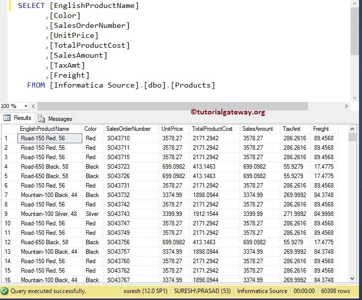
Before we start configuring the router transformation in Informatica, First connect to Informatica repository service. In order to connect with Repository service we have to provide the Admin Console credentials so, Please provide the appropriate Username and Password and click on Connect button as shown below.
TIP: Here you have to provide the Admin Username and password that you specified while installing the Server.

Once you have connected successfully, Please navigate to Source Analyzer and define your Sources. In this Informatica Router Transformation example, we use the [Products] table from the SQL Server database as our source definitions. Please refer to Database Source to understand the steps involved in creating a source definition

Please navigate to Target Designer and define the Target. In this Informatica Router Transformation example, we are using the already created SQL tables (Router1, Router2, and Router3) as our target definitions. Please refer Create Target table using Source Definition to understand the steps involved in creating a target definition

In order to create a new mapping, Please navigate to Mappings menu in Menu Bar and select the Create.. option. Here, you have to write a unique name for this mapping (m_Router_Transformation) and click OK button.
Next, Drag and drop the [Products] source definition from Sources folder to the mapping designer. Once you drag the source, the PowerCenter designer will automatically create the default transformation called source qualifier.
In order to create Router transformation in Informatica, Please navigate to Transformation menu in Menu Bar and select the Create.. option as we shown below.

Once you click on the Create.. option, Create Transformation window will be opened as shown below. Please select the Informatica Router Transformation from the drop-down list and specify the unique name (rtr_Sales) for this transformation and click on Create button

Once you click on the Create button, router transformation will be added to the mapping designer. In order to route the data, router Transformation requires some data so, please connect the Source definition with the transformation by dragging the required fields.

From the above screenshot, you can observe that we have our INPUT data. Let us define the output groups so, Double click on the Informatica Router transformation to provide the route conditions. From the below screenshot you can see the list of available properties in the Transformation tab:
- Select Transformation: By default, it will select the transformation you clicked on.
- Rename: This button will help you to rename the router transformation to a more meaningful name.
- Make Reusable: If you check mark this option then, this transformation will become reusable transformation.
- Description: Please provide a valid description of this transformation.

Below screenshot will show you the list of available options in the Informatica Router Transformation Ports tab:
- Port Name: List of available column names. By clicking the New column button you can add new columns and by clicking the scissors button you can delete the unwanted columns.
- I: Columns that are check-marked under this section are the Input columns.
- O: Columns that are check-marked under this section are the router transformation Output columns. If you unchecked any column then, that column will not be available to load in the target table.

Within the Groups tab, we have to define the group names and condition we want to use. From the below screenshot, you can observe that we created two groups (LEAST SALES and MEDIUM SALES).
TIP: The router transformation in Informatica will automatically create the default group (i.e., DEFAULT 1). Records which does not belong to above-mentioned groups will be stored in this group.

Let us provide the expression or condition for the First group (Least Sales) by clicking the arrow button as we shown below. This will open the Expression Editor to write a custom expression.
Here, we want the records whose Sales Amount is less than 400 so, we are writing the below-shown expression (SalesAmount < 400).

Next, provide the expression or condition for the Second group (Medium Sales) by clicking the arrow button and write the condition (SalesAmount >= 400 AND SalesAmount < 2000).

All the remaining rows will be acted as default output and they will be stored in DEFAULT 1 group (Sales Amount > 2000)

Once you finish configuring the properties, Click OK to close the Informatica Router Transformation window.
Next, Drag and drop the target definitions (Router 1, Router2 and Router3) from Targets folder to the mapping designer as shown below.

Next, Please connect the LeastSales (Output Group 1) with the first target definition (Router 1), MediumSales (Output Group 2) with Router 2 and Default 1(Default Group) with Router 3

Before we close the Mapping, Let us validate the mapping by going to Mapping Menu bar and selecting the Validate option.
Once we finish creating the Mapping we have to create the workflow for it. PowerCenter Workflow manager provides two approaches to create a workflow.
In this Informatica Router Transformation example, we will create the Workflow manually. In order to create a new workflow, Please navigate to Workflows Menu and select the Create option.
This will open Create Workflow window as shown below. Please provide the unique name (wf_Router_Transformation) and leave the default settings.

Once we created the workflow, our next step is to create a session task for our mapping.
NOTE: We strictly recommend to refer Workflow article to understand the steps involved in creating Workflow manually.
There are two types of sessions:
- Non-reusable Session Task: Please refer Session article to understand the steps involved in it.
- Reusable Session Task: Please refer Reusable Session article to understand the steps involved in it.
For this Informatica Router Transformation example, we are going to create Non-reusable Session. Please navigate to Tasks Menu and select the Create option to open the Create Task window. Here you have to select the Session as Task type (default) and enter a unique name (S_Router_Transformation) for the session.
Once you click on the Create button, a new window called Mappings will be opened. Here you have to select the mapping you want to associate with this session. From the below screenshot you can observe that we are selecting the mapping (m_Router_Transformation) that we created earlier (in Step 3).

Double click on the Session Task to configure it. Although we have to configure Sources, targets, and some common properties, we not explaining any of them. We strictly recommend visiting the Session article to understand the properties.
From the below screenshot you can observe that the Router Transformation in Informatica workflow is a valid one. Now, Let us start the Workflow by navigating to Workflows menu and selecting the Start Workflow option.

Once you select the Start Workflow option, the PowerCenter Workflow monitor will be opened to monitor the workflow. From the below screenshot you can observe that our workflow is executed without any errors.

Let us open the SQL Server Management Studio to show you the result of [Router 1] (i.e., an output of the Least Sales group)

Let’s see the result in [Router 2] Table in SQL Server. The following screenshot will show you the output of the Medium Sales group

Let’s see the result in [Router 3] Table in SQL Server. The following screenshot will show you the output of the Default group. Please refer to Filter article.

Sequence Generator Transformation in Informatica
The Sequence Generator Transformation in Informatica is a connected transformation that generates numeric values. We can mainly use this transformation to generate primary keys, foreign keys or to fill or replace the missing primary keys with unique ones.
The Sequence Generator Transformation in Informatica has two output ports only NEXTVAL and CURRVAL and it will not allow the users to create new ports or alter, delete existing ports.
In this article, we are going to explain the steps involved in configuring the Informatica Sequence Generator Transformation with an example. For this example, we are going to use the below show data

Before we start configuring the sequence generator transformation in Informatica, First connect to the repository service. In order to connect with the Repository service, we have to provide the Admin Console credentials. So, Please provide the appropriate Username and Password and click on Connect button.
TIP: Here you have to provide the Informatica Admin Username and password that you specified while installing the Server.

Once you connected successfully, Please navigate to Source Analyzer and define your Sources. In this Informatica Sequence Generator Transformation example, we are using the [Employ] table from the SQL Server database as our source definitions. Please refer to Database Source to understand the steps involved in creating a source definition

Please navigate to Target Designer and define the Target. In this Informatica Sequence Generator Transformation example, we are using the already created SQL table (Sequence Generator) as our target definition. Please refer Create Target table using Source Definition to understand the steps involved in creating a target definition

In order to create a new mapping, Please navigate to Mappings menu in Menu Bar and select the Create.. option. This will open the Mapping Name window. Here, you have to write a unique name for this mapping (m_Sequence_Generator) and click OK button.
TIP: Please refer Mapping article to understand the steps involved in creating Mapping.

Next, Drag and drop the [Employ] source definition from Sources folder to the mapping designer. Once you drag the source, the PowerCenter designer will automatically create the default transformation called source qualifier.
In order to create Sequence Generator transformation in Informatica, Please navigate to Transformation menu in Menu Bar and select the Create.. option as we shown below.

Once you click on the Create.. option, Create Transformation window will be opened. Please select the Informatica Sequence Generator Transformation from the drop-down list and specify the unique name (seq_Employee) for this transformation and click on Create button

Once you click on the Create button, the Sequence Generator transformation will be added to the mapping designer. Next, Drag and drop the target definition (sequence generator) from Targets folder to the mapping designer and connect the source qualifier, Transformation with the target definition. Please use the Autolink.. option to connect them.

From the above screenshot, you can observe that Informatica Sequence Generator transformation generates two default items NEXTVAL and CURRVAL. NEXTVAL port is the one we have to assign for the Employee_ID and we have to assign the CURRVAL inside the transformation editor.
Double click on the Informatica Sequence Generator transformation to generate the sequential numbers. From the below screenshot you can see the list of available properties in the Transformation tab:
- Select Transformation: By default, it will select the transformation you clicked on.
- Rename: This button will help you to rename the Sequence Generator transformation to a more meaningful name.
- Make Reusable: If you check mark this option then, this transformation will become reusable transformation.
- Description: Please provide a valid description of this transformation.

Below screenshot will show you the list of available options in the Informatica Sequence generator transformation Ports tab:
- Port Name: List of available column names. By clicking the New column button you can add new columns and by clicking the scissors button you can delete the unwanted columns.
- I: Sequence generator transformation will not allow Input columns.
- O: Columns that are check-marked under this section are the sequence generator transformation Output columns. If you unchecked any column then, that column will not be available to load in the target table.

Below screenshot will show you the list of available options in the Informatica Sequence generator transformation Properties tab.
- Start Value: Please specify the value you want to start with. For example 1 for ID’s or Primary key value of starting or Maximum value plus one.
- Incremented By: Please specify the value you want to use as sequence incremented. For example, 1 means value will be incremented by 1 (1, 2, 3, …..) or if you specify 2 then values will be 2, 4, 6, 8…
- End Value: Please specify the end value here. For example, if you specify 10 as End Value then, a sequence will stop when it reaches 10.
- Current Value: Please specify the Current value here. For example, if you specify 3 as the current Value then, the sequence will start from 3 and increment the value using Incremented By option until it reaches End Value. Once it reaches the End value, it will repeat the cycle starting from Start Value
- Cycle: Please specify whether you want to repeat the cycle or Not. For example, if your End Value is less than the existing rows then it is good to select the Cycle option OR if you want to repeat the same series of numbers then select this option.
- Reset: Please specify whether you want to reset the sequence for every single session or Not.

From the below screenshot you can observe the properties we specified. Here, Sequence generator will start the sequence with value 1 and incremented by 2 until it reaches 6. After reaching end value, Sequence generator will start the sequence with value 0 (Start Value)

Once you finish configuring the properties, Click OK to close the transformation window.

Before we close the Mapping, Let us validate the mapping by going to Mapping Menu bar and selecting the Validate option.
Once we finish creating the Mapping we have to create the workflow for it. PowerCenter Workflow manager provides two approaches to create a workflow.
In this Informatica Sequence generator transformation example, we will create the Workflow manually. In order to create a new Workflow, Please navigate to Workflows Menu and select the Create option. This will open Create Workflow window as shown below. Please provide the unique name (wf_Rank_Transformation) and leave the default settings.

Once we created the workflow, our next step is to create a session task for our mapping.
NOTE: We strictly recommend to refer Workflow article to understand the steps involved in creating Workflow manually.
There are two types of sessions:
- Non-reusable Session Task: Please refer Session article to understand the steps involved in it.
- Reusable Session Task: Please refer Reusable Session article to understand the steps involved in it.
For this Informatica Sequence generator transformation example, we are going to create Non-reusable Session. Please navigate to Tasks Menu and select the Create option to open the Create Task window. Here you have to select the Session as Task type (default) and enter a unique name (S_Rank_Transformation) for the session.
Once you click on the Create button, a new window called Mappings will be opened. Here you have to select the mapping you want to associate with this session. From the below screenshot you can observe that we are selecting the mapping (m_Rank_Transformation) that we created earlier (in Step 3).

Double click on the Session Task to configure it. Although we have to configure Sources, targets, and some common properties, we are explaining only a few properties. We strictly recommend visiting the Session article to understand the remaining properties.
From the below screenshot you can observe that the Sequence Generator Transformation in Informatica workflow is a valid one. Now, let us start the Workflow by navigating to the Workflows menu and selecting the Start Workflow option.

Once you select the Start Workflow option, the PowerCenter Workflow monitor will be opened to monitor the workflow. From the below screenshot you can observe that our workflow is executed without any errors.

Let us open the SQL Server Management Studio to check whether we successfully generated the Employee_Id using the Sequence Generator Transformation in Informatica

Let us change the Properties of Start Value, End Value and Incremented Value as shown below. Next, refresh the mapping and start the Workflow.

Let us open the SQL Server Management Studio to check whether we successfully generated the sequential Employee_Id using the Sequence Generator Transformation in Informatica

Sorter Transformation in Informatica
The Sorter Transformation in Informatica is used to sort the source data in either Ascending or Descending order, similar to SQL command ORDER BY Statement.
In this section, we are going to demonstrate the steps involved in configuring the Informatica Sorter Transformation with an example. For this example, we are going to use the below show data
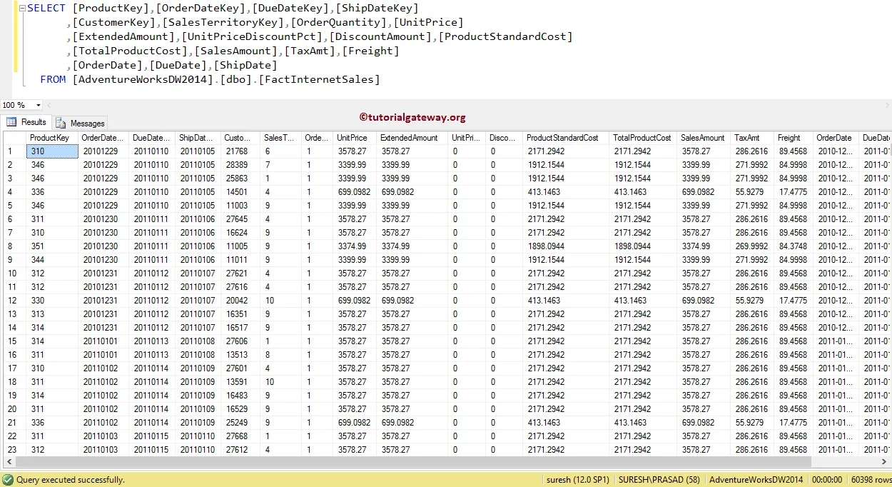
Before we start the Informatica Sorter Transformation demo, First, connect to the Informatica repository service. For this, provide the Admin Console credentials (Username and Password) and click on the Connect button

Once you connected successfully, Please navigate to Source Analyzer to set our Sources. In this Informatica Sorter Transformation example, we are using the already created SQL table (Fact Internet Sales) as our source definition. Please refer Database Source to know the steps involved in creating a source definition

To create a new mapping for Informatica Sorter Transformation, Please navigate to the Mappings menu in Menu Bar and select the Create.. option. Here, you have to write a unique name for this Mapping and click the OK button.
TIP: Please refer Mapping article to understand the steps involved in creating Mapping.

Next, Drag and drop the [Fact Internet Sales] source definition from Sources folder to the mapping designer. Once you drag the source, the PowerCenter designer will automatically create the default transformation called the source qualifier.
To create a sorter transformation in Informatica, Please navigate to the Transformation menu in Menu Bar and select the Create.. option.

It opens a Create Transformation window, as shown below.

Please click on the arrow to select the required transformation from the drop-down list. Let us choose the Informatica Sorter transformation

Next, Please specify the unique name for this Informatica Sorter transformation and click on Create button

Once you click on the Create button, the Informatica Sorter transformation will be added to the mapping designer. In order to perform sorting, transformation requires some data so, we have to connect it with Source definition.
 The PowerCenter Designer provides multiple ways to connect the source qualifier with the newly created Sorter Transformation in Informatica. For this example, we are right-clicking on the empty space and selecting the Autolink.. option from that context menu.
NOTE: The Mapping designer allows us to delete the wrong mapping by selecting the link and deleting it.

From the above screenshot, you can observe that we successfully connected the source qualifier to the sorter transformation.
Double click on the Informatica Sorter transformation to configure the sort properties. Below window will show you the list of available properties in the Transformation tab:
- Select Transformation: By default, it will select the transformation you clicked on.
- Rename: This button will help you to rename the sorter transformation to a more meaningful name.
- Make Reusable: If you check mark this option then, this transformation will become reusable transformation.
- Description: Please provide the valid description about this transformation.

The below screenshot will show you the list of available options in the Ports tab of an Informatica Sorter Transformation:
- Port Name: List of available column names. By clicking the New column button you can add new columns and by clicking the scissors button you can delete the unwanted columns.
- I: Columns that are check marked under this section are the Sorter transformation Input columns.
- O: Columns that are check marked under this section are the Sorter transformation Output columns. If you unchecked any column then, that column will not be available to load in the target table.
- Key: Please checkmark the Column(s) that you want to use as Sort column. For example, If you want to sort the data by Unit Price and Order Quantity then you have to checkmark both of them.
- Direction: Here we have to select the Sort direction. This Informatica Sorter Transformation provides two options: Ascending order (A to Z) and Descending Order(Z to A)

To understand the Sorter Transformation in informatica, we are sorting one column with Ascending order and another with Descending order. From the below screenshot you can observe that, we are sorting the [Sales Amount] in Descending Order

Next, we are sorting the [Freight] in Ascending order. It means,
- First data is sorted by the [Sales Amount] in Descending Order and then
- Second, data will be sorted by the [Freight] in Ascending order.

Click OK to finish configuring the Sorter Transformation.
First, Drag and drop the target definition from the Targets folder to the mapping designer. Next, We have to connect it with the target definition. Please use the Autolink.. option to connect them.
TIP: Please refer to Create Target Table article to understand importing the target definition from the SQL Database.

Before we close the Mapping, Let us validate the Informatica Sorter Transformation mapping by going to Mapping Menu bar and selecting the Validate option.
Once we finish creating the Mapping we have to create the workflow for it. The PowerCenter Workflow manager provides two approaches to creating a workflow.
In this Informatica Sorter Transformation example, we created the Workflow manually. We strictly recommend to refer Workflow article to understand the steps involved in creating Workflow manually. Once we created the workflow, our next step is to create a session.
There are two types of sessions:
- Non-reusable Session Task: Please refer Session article to understand the steps involved in it.
- Reusable Session Task: Please refer Reusable Session article to understand the steps involved in it.
For this Sorted Transformation in Informatica example, we are going to create Non-reusable Session. In order to create Non-reusable Session, Please navigate to Tasks Menu and select the Create option to open the Create Task window. Here you have to select the Session as Task type (default) and enter a unique name for the session.
Once you click on the Create button, a new window called Mappings will open. Here we have to select the mapping you want to associate with this session. From the below screenshot you can observe that we are selecting the mapping that we created earlier (in Step 2).

Although we have to configure sources, Target, and some common properties, we are explaining only two properties. We strictly recommend visiting the Session article to understand the remaining properties.
From the below screenshot you can observe that, we changed the Target Load Type option from Bulk to Normal mode and check marked the Truncate target table option to truncate the existing data from the destination table.

From the below screenshot you can observe that Our workflow is a valid one. Now, let us start the Informatica Sorter Transformation Workflow by navigating to the Workflows menu and selecting the Start Workflow option.

Once you select the Start Workflow option, the PowerCenter Workflow monitor will be opened to monitor the workflow. From the below screenshot you can observe that our workflow is executed without any errors.

Let us open the Management Studio to check whether we successfully transferred the sort data from Adventure Works DW to the target database. Please refer ORDER BY Statement article in SQL Server Tutorial.

Remove Duplicates Using Sorter Transformation in Informatica
In this article, we are going to explain how to remove duplicates using Sorter Transformation in Informatica with an example. For this example, we are going to use the below show data
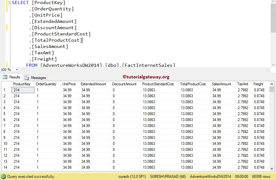
From the above screenshot, you can observe that we have 60398 records with many duplicates. Our task is to select distinct records or remove duplicates using sorter transformation in Informatica.
Before we start removing duplicates using sorter, connect to Informatica repository service. For this, we have to provide the Admin Console credentials. So, Please provide the appropriate Username and Password and click on the Connect button.
TIP: Here, provide the Admin Username and password that you specified while installing the Server.

Step 1: Creating Source Definition
Once you connected successfully, Please navigate to Source Analyzer and define our Sources. In this example, we are using the already created SQL table (Internet Sales) as our source definition. Please refer Database Source to understand the steps involved in creating a source definition

Step 2: Creating a Target Definition
Please navigate to Target Designer and define the Target(s). In this example, we are using the already created SQL table (Fact Internet Sales) as our target definition. Please refer Create Target table using Source Definition to understand the steps involved in creating a target definition

To create a new mapping, Please navigate to the Mappings menu in Menu Bar and select the Create.. option. It will open the Mapping Name window. Here, you have to write a unique name for this Mapping and click the OK button.
TIP: Please refer Mapping article to understand the steps involved in creating Mapping.

Next, Drag and drop the [Internet Sales] source definition from Sources folder to the mapping designer and create a sorter transformation. The sorter transformation requires some data to remove the duplicates. So, we have to connect the Source definition with the transformation using the Autolink.. option.
TIP: Please refer to Sorter Transformation article to understand the steps involved in configuring Sorter transformation.

Double click on the Sorter transformation to configure the properties. From the below screenshot, you can observe the list of available properties in Properties tab. In this example, we want to remove duplicate records so, checkmark the Distinct property.
TIP: This will act as SQL SELECT DISTINCT Statement

Next, If you observe the Ports tab, Sorter Transformation is sorting all the input columns in ascending order. Remember, you don’t have to do anything here.
Click the OK button to finish configuring the properties.

Next, Drag and drop the [Duplicate Sorter Transformation in Informatica] target definition from Targets folder to the mapping designer and connect the Sorter Transformation with the target definition. Please use the Autolink.. option to connect them.

Before we close the Mapping, Let us validate the mapping by going to Mapping Menu bar and selecting the Validate option.
Step 4: Creating a Workflow
Once we finish creating the Mapping we have to create the workflow to remove Duplicates using Sorter Transformation in Informatica. PowerCenter Workflow manager provides two approaches to create a workflow.
In this example, we created the Workflow manually. Once we created the workflow, our next step is to create a session.
We strictly recommend referring Workflow article to understand the steps involved in creating Workflow manually.
Step 4(a): Creating Session
There are two types of sessions:
- Non-reusable Session Task: Please refer Session article
- Reusable Session Task: Please refer Reusable Session article
For this example, we are going to create Non-reusable Session. To create Non-reusable Session in Informatica, Please navigate to Tasks Menu and select the Create option to open the Create Task window. Here you have to choose the Session as Task type (default) and enter a unique name for the session.
Once you click on the Create button, a new window called Mappings will open. Here we have to select the Mapping you want to associate with this session. From the below screenshot, you can observe that we are choosing the Mapping that we created earlier (in Step 3).

Although we have to configure sources, Target, and some common properties, we are not going to explain them here. Please refer to Session article to understand the properties.
From the below screenshot, you can observe that the Remove Duplicates Using Sorter Transformation in Informatica workflow is a valid one. Now, let us start the Workflow by navigating to the Workflows menu and selecting the Start Workflow option.

Once you select the Start Workflow option, the PowerCenter Workflow monitor will be opened to monitor the workflow. From the below screenshot, you can observe that our workflow executed without any errors.

Let us open the SQL Server Management Studio to check whether we successfully remove duplicates / transferred the distinct records from Adventure Works DW to the target database.

From the above screenshot, you can observe that there are only 158 distinct records out of 60398. Let see the same by writing the Distinct query in SQL

Source Qualifier Transformation in Informatica
The Source Qualifier Transformation in Informatica is an Active, and Connected transformation. While creating a mapping, this is the default transformation generated by the power Center Designer.
This Informatica Source Qualifier Transformation converts the source data types to the native data types. In real-time, you can use this Informatica Source Qualifier Transformation to Join Multiple Sources, Write a custom query, Filter Rows, or Select Unique Records
For this Informatica Source Qualifier Transformation example, we are going to use the below show data (Employee table)

and the Department table

and the Destination table is Source Qualifier. As you can see, it is an Empty table

Before we start configuring the Informatica source qualifier transformation, First connect to the repository service by providing the Admin Console credential.
TIP: Here you have to provide the Admin Console Username and password that you specified while installing the Server.
Navigate to Analyzer and define your Sources. As we said before, we are using Employee and Department tables from the SQL Server database as our Informatica source definitions. Please refer Database to understand the creation of the source definition

Please navigate to Target Designer to define the Target. In this example, we are using the existing SQL table (SourceQualifier) as our target definition. You can refer to Create Target table using Definition to understand the process of creating a target definition

To create a new mapping, Please navigate to Mappings menu in Menu Bar and select the Create.. option. This will open the Mapping Name window as shown below. Here, you have to write a unique name for this mapping (m_Source_Qualifier) and click OK button.

Drag and drop the Employee, and Department from Sources folder to the mapping designer. Once you drag the source, Power Center designer will automatically create the source qualifier transformation (default transformation) for you.

Let me remove the Department Table Source Qualifier

Next, we are adding the Department columns to the Employee source qualifier. This is one way of adding two tables

Let me remove the SQ_Employee (Employee Source Qualifier as well).
To explicitly create Source Qualifier transformation in Informatica, Please navigate to Transformation menu in Menu Bar. Next, select the Create.. option will open the Create Transformation window as shown below.
Please select the Source Qualifier Transformation from the drop-down list and provide the unique name (SQ_EmployeeDetails) for this transformation and click on Create button

That will open the below shown window as we shown below. Click OK to select the Department table and Employee table.

Now you can see the same image that you have seen before

Double click on the Source Qualifier transformation to see, and alter the properties. Below screenshot shows you the list of available properties in the Transformation tab:
- Select Transformation: By default, it will select the transformation you selected (or clicked on).
- Rename: This button helps you to rename the Source Qualifier transformation name.
- Description: Use this place to provide a valid description of this transformation.

Below screenshot shows you the available options in the Ports tab:
- Port Name: List of available column names. Use New column button to add new columns, scissors button to delete the unwanted columns. Here, we are deleting the DeptID column because it is a duplicate column
- I: Input columns.
- O: Here, Columns that are check-marked are the Source Qualifier transformation Output columns. If you unchecked any column then, that column will not be available to load in a target table.

Under Properties we have:
- SQL Query: Use this property to write a Custom SQL Query. This query will replace the default SQL Query generated by it.
- User Defined Join: Use this property to Join multiple data sources.
- Filter: This property is used to filter the selected rows. It is Equal to the Where Clause in SQL, or any database.
- Number of Sorted Ports: This is used to sort the data. Similar to Order By Clause
- Tracing Level: Specify how you want to trace (Detailed)
- Select Distinct: This property is used to select the Distinct (Unique records). Similar to SQL DISTINCT
- Pre SQL: Use this property to run the Command against the Source before the Integration Service Starts.
- Post SQL: Use this property to run the Command against the Source After the Integration Service Ends.

Let me use the User Defined Join property to Join the Employee table and Department table

As you can see we are using the below condition. You can refer SQL Joins article to understand the condition, or Joiner Transformation to understand the Joining concept.

Next, Drag and drop the target definition (SourceQualifier) from Targets folder to the mapping designer. Next, connect the source qualifier Transformation with the target definition. Please use the Autolink.. option to connect them.
Before we close the Mapping, Let us Save, and Validate the mapping by going to Mapping Menu bar, and select the Validate option.

After you finish creating the Mapping, we have to create the workflow for it. Power Center Workflow manager provides two approaches to create a workflow.
In this example, we will create the Workflow manually. To do so, Please navigate to Workflows Menu and select the Create option. This will open Create Workflow window as shown below. Please provide the unique name (wf_Source_Qualifier) and leave the default settings.

Once we created the workflow, our next step is to create session task for our mapping.
Create Source Qualifier Session
There are two types of sessions:
For this example we created a Reusable Session, and named it as s_EmployeeDept_fromSQL_ToSQL for the session.Please link the Start Task, and the Session Task. Next, navigate to Workflows Menu and select the Validate option to validate the Workflow.

From the above screenshot you can observe that the Source Qualifier Transformation in Informatica workflow is a valid one.
Now, Let me start the Workflow. To do so, navigate to Workflows menu, and select the Start Workflow option.

Let us open the SQL Server to check whether we successfully performed the Joining using the Source Qualifier Transformation in Informatica

SQL Transformation in Informatica
The SQL Transformation in Informatica is used to write or use SQL Queries in the middle of the transformation. Using this SQL transformation, you can Insert, Delete, or Update rows in a Database. If you are familiar with queries, then you can use this transformation.
Here, we show you how to use Informatica SQL Transformation to write transact Queries within the transformation with an example. For this example, we are going to use SP Source and Destination tables.
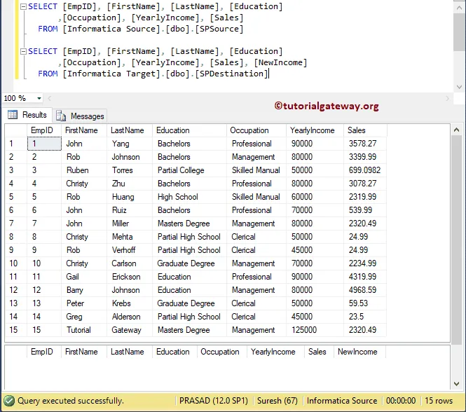
This example shows how to use SQL Transformation in Informatica to run the Script or Query against a database. Before we start configuring, First, connect with the repository service.
To do so, enter the Admin Console Username and Password you specified while installing the Server.
Once you connected successfully, Please navigate to Source Analyzer and define your Informatica Sources. In this example, we are using the Sp Source table from the database as our source definitions. Please refer Database Source article.

Please navigate to Target Designer to define the Target. In this example, we are using the existing table (SP Destination) as our target definition. You can refer to Create Target table using Source Definition article.

To create a new mapping for Informatica SQL Transformation, Please navigate to the Mappings menu and select the Create.. option.

Once you select the Create.. option, a new Mapping Name window opens. Let me provide the mapping name and click the OK button.

Drag and drop the SP Source from Sources folder to the mapping designer. Once you drag the source, Power Center Designer will automatically create the Source Qualifier Transformation (default transformation) for you.

To create SQL Transformation in Informatica, Please navigate to the Transformation menu and select the Create.. option

Selecting the Create.. option will open the Create Transformation window. Please select the SQL Transformation and provide the unique name and click on Create button

Clicking the Create button will pop up a new window called Informatica SQL Transformation.
- Query Mode: Use this option to write Query directly inside the transformation. You can Insert, Delete, or Update rows in a Database
- Script Mode: If your Server query is saved in a Script file, then you can use this option. If you select this option, then you have to pass the Script file name.
- DB Type: Please select the Database type. For example, SQL, Oracle, etc.
- Static Connection: If you want the connection to be static, then select this option.
- Dynamic Connection: Select this option for Dynamic connection.
- Transformation in Passive Mode, By default, it is in Active mode. By checking this option, you can convert it to Passive Mode.

For this demo, we will write a Select Query. So, let me change the DB Type to Microsoft SQL Server and select the Query Mode

By clicking OK will create an Active SQL Transformation In Informatica for you.

Let me drag all the fields that are available in source definition to SQL Transformation in Informatica. It automatically creates a set of Input and Output fields.

Double click on the SQL Transformation in Informatica mapping editor to edit or configure the transformation. Under the Ports tab, you can see the auto-generated output ports from the source definition inputs.

Ports: This is the most crucial tab in this transformation. It is where we are going to write a Query or selecting the script. Before we start writing the script, Let me add one extra field because our target table has a New Income column. To do so, click on the New field button

It adds an extra column to the output section

Please rename the column to New Income and change its Native type. Next, change the Native Type of each Input and Output filed to match the Source and target definition. Once you have done with it, click on the Arrow beside the Query.

It opens an Editor with available parameters. As you can see, we are using Select Statement to select Yearly income from the SP Source table and adding 45999 to it for each employee record. And the Query is:
SELECT YearlyIncome + 45999 FROM SPSource
WHERE EmpID = ?EmpID?

Check whether everything is OK or not. Remember, whatever the data that we got from the Select Statement saved as Output and our output field is New Income. So, New Income = Yearly Income + 45999 where Emp ID = 1, 2, 3, .. 15

Next, Drag and drop the target definition (SP Destination) from Target’s folder to the mapping designer. Next, connect the SQL Transformation Output fields with the target definition using the Autolink.. option.

Before we close the Mapping, Let us Save, and Validate the mapping by going to Mapping Menu bar, and select the Validate option.
After you finish creating the Mapping, we have to create the workflow for it. PowerCenter Workflow manager provides two approaches to create a workflow.
In this Informatica SQL Transformation example, we will create the Workflow manually. To do so, Please navigate to Workflows Menu and select the Create option.

It opens the Create Workflow window to provide the unique name and leave the default settings

Once we created the workflow, our next step is to create a session task for our mapping.
There are two types of sessions:
For this Informatica SQL Transformation example, we created a Non-reusable Session. To create Non-reusable Session, Please navigate to Tasks Menu and select the Create option.

Please provide a unique name for this session. Here, we are naming it as s_Employee. Once you click on the Create button, a new window called Mappings will open. Here you have to select the mapping that you want to associate with this session.

Double click on the Session task will open the Edit Tasks window. Within Properties Tab
$Source connection value: This property will store the relational source information in the $Source variable. So, click on the Arrow we marked below, and select the Source as the source information.

$Target connection value: This property will store the relational target information in the $Target variable. So, click on the Arrow we marked below, and select the below Target as the Target information.

Within the mappings tab, we have to configure the Source and Target Connections. First, let us configure the source connections by clicking on the SQ_SPSource source present in the Sources folder.
Within the Connections, click on the Arrow button beside the Relational type, and use the Connection variable that we created in our previous step, i.e., $Source

Now, we have to configure the Target Connection. So, click on the SPDestination present in the Targets folder. Within the Connections, click on the Arrow button beside the Relational type, and use the Connection variable $Target

Lastly, we have to configure the Informatica SQL Transformation. So, click on the Employee present in the Transformations folder.
Within the Connections, click on the Arrow button beside the Relational type, and use the Connection variable $Source. It is because we used the Select Statement to select records from Source.

After completing the Session configuration, navigate to Workflows Menu, and select the Validate option to validate the Workflow.

Now, Let me start the SQL Transformation in Informatica Workflow. To do so, navigate to the Workflows menu and select the Start Workflow option.

Open the Management Studio and write the following query.

Stored Procedure Transformation in Informatica
The Stored Procedure Transformation in Informatica helps you to use or call Stored procedures inside the Informatica Workflow. Using this transformation, you can operate Drop or Recreate Indexes, Check for Space in a Database, performing Complex Calculations.
This article shows how to use this Informatica Stored procedure Transformation to Rollback the passing records with an example. For this example, we are going to use SP Source and Destination tables.
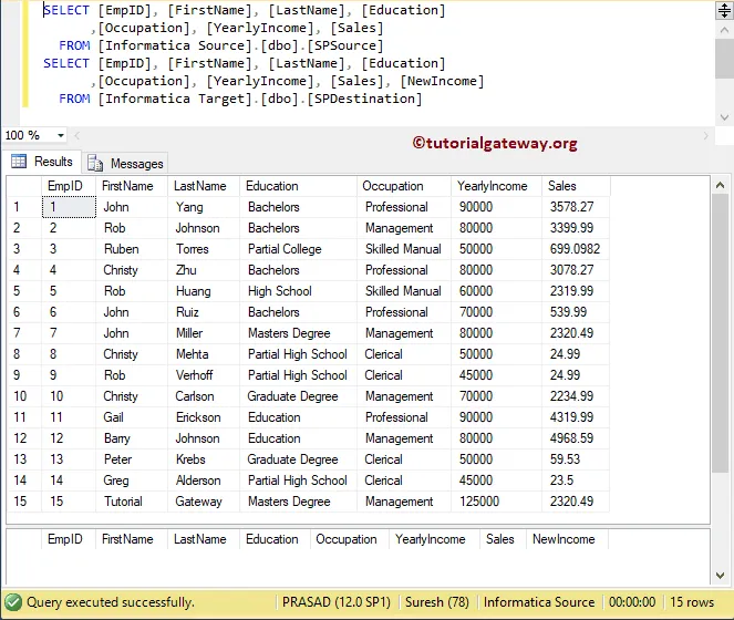
And the Stored procedure that we are going to use is:

From the above screenshot, you can see, that the stored procedure has one input parameter and one output parameter
TIP: We explained everything about the Stored procedure and its functionalities in the SQL Server tutorial. I suggest you refer Stored Procedures article to understand the topic.
Let us see how to use Stored Procedure Transformation in Informatica to call stored procedures inside a Workflow. Before we start configuring, First, let me connect with the Informatica repository service.
To do so, we have to provide the Admin Console credentials. So, Please provide the appropriate Username and Password you specified while installing the Server.
Once you connected successfully, Please navigate to Source Analyzer and define your Sources. Here, we are using the Sp Source table from the SQL database as our source definitions. Please refer Database Source to understand the steps in creating source definition

Please navigate to Target Designer to define the Informatica Stored Procedure Transformation Target. In this example, we are using the existing table (SP Destination) as our target definition. You can refer to Create Target Table to understand the process of creating a target definition

To create a new mapping, Please navigate to the Mappings menu in Menu Bar and select the Create.. option.

Once you select the Create.. option, a new Mapping Name window will open. Let me provide m_StoreProc as the mapping name and click the OK button.
TIP: Please refer Mapping article to understand the procedure to create Mapping

Drag and drop the SP Source from Sources folder to the mapping designer. Once you drag the source, Power Center Designer will automatically create the Source Qualifier Transformation (default transformation) for you.

To create Stored Procedure Transformation in Informatica, Please navigate to the Transformation menu in Menu Bar. Next, select the Create.. option

Selecting the Create.. option will open the Create Transformation window. Please select the Stored procedure Transformation from the drop-down list and provide a unique name (sp_Testing) and click on Create button

Clicking the Create button will pop up a new window called Import Stored Procedure. Please select the ODBC connection that will connect with the Source. It is where our Stored procedure was created. To create a new ODBC Connection, please refer to the ODBC Connection article.
From the below screenshot, see that we are selecting the spUpdateCust stored procedure.

By clicking OK will create a Informatica Stored Procedure Transformation for you. As you can see from the below screenshot, it has three ports: Return_value, EmpId, and New Income

Next, Drag and drop the target definition (SPDestination) from the Targets folder to the mapping designer.

Next, we are connecting the EmpId from Source Qualifier to Transformation. Because spUpdateCust accepts one input parameter (EmpId) to return New Income output.

Double click on the Informatica Stored Procedure Transformation to see and alter the properties. Below screenshot shows you the list of available properties in the Transformation tab:
- Select Transformation: By default, it will select the transformation you selected (or clicked on).
- Rename: This button helps you to rename the Transformation name.
- Description: Use this place to provide a valid description of this transformation.

Below screenshot shows you the available options in the Informatica stored procedure transformation Ports tab:
- Port Name: List of available column names. Use the New column button to add new columns, scissors button to delete the unwanted columns.
- I: Input columns.
- O: Here, Columns that are check-marked are the Output columns.

Within the properties tab, click on the Arrow button beside the Connection Information type, and use the Connection variable $Source because we used the SP that exists in information Source.

Drag and drop all the fields that exist in source qualifier Transformation to target definition. Please use the Autolink.. option to connect them. Next, connect the NewIncome field in transformation with target definition.

Before we close the Mapping, Let us Save, and Validate the mapping by going to Mapping Menu bar, and select the Validate option.
Create Workflow
After you finish creating the Informatica Stored Procedure Transformation Mapping, we have to create the workflow for it. PowerCenter Workflow manager provides two approaches to create a workflow.
In this example, we will create the Workflow manually. To do so, Please navigate to Workflows Menu and select the Create option.

It opens the Create Workflow window. Please provide the unique name (wf_StoredProc) and leave the default settings.

Once we created the workflow, our next step is to create a session task for our mapping.
There are two types of sessions:
For this Informatica Stored Procedure Transformation example, we created a Non-reusable Session. To create Non-reusable Session, Please navigate to Tasks Menu and select the Create option.

Please provide a unique name for this session. Here, we are naming it as s_StoredProc. Once you click on the Create button, a new window called Mappings will open. Here you have to select the Mapping that you want to associate with this session, i.e., m_Storedproc.

Double click on the Session task will open the Edit Tasks window. Within Properties Tab
$Source connection value: This property will store the relational source information in the $Source variable. So, click on the Arrow we marked below, and select the Source as the source information.

$Target connection value: This property will store the relational target information in the $Target variable. So, click on the Arrow we marked below, and select the Target as the Target information.

Within the mappings tab, we have to configure the Source and Target Connections. First, let us configure the source connections by clicking on the SQ_SPSource source present in the Sources folder.
Within the Connections, click on the Arrow button beside the Relational type. And use the Connection variable that we created in our previous step i.e., $Source

Now, we have to configure the Informatica Stored Procedure Transformation Target Connection. So, click on the SPDestination present in the Targets folder. Within the Connections, click on the Arrow button beside the Relational type, and use the Connection variable $Target

Here, we can also configure the connection information. To do so, click on the SP_Testing present in the Transformations folder.

Next, navigate to Workflows Menu and select the Validate option to validate the Workflow.

Now, Let me start the Informatica Stored Procedure Transformation Workflow. To do so, navigate to the Workflows menu and select the Start Workflow option.

Let us open the Management Studio and write the following SQL Query.

Transaction Control Transformation in Informatica
The Transaction Control Transformation in Informatica allows you to control the Transactions within the Transformation. Using this transaction Control Transformation, you can Commit or Rollback the records (or rows) passing through it.
For this Informatica Transaction Control Transformation example, we are going to use SP Source and Destination tables.
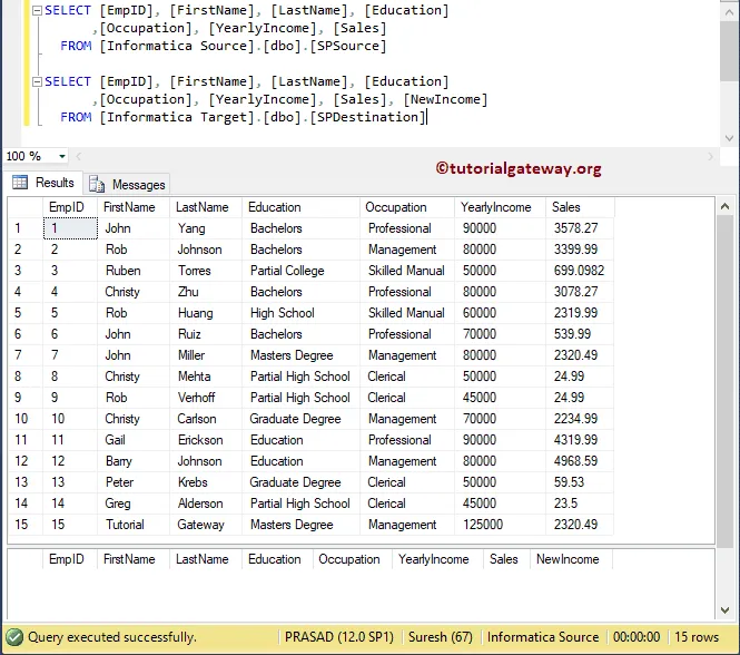
In this example, we will show you how to use Transaction Control Transformation in Informatica to perform the Rollback Transaction. Before we start configuring, First, let me connect with the repository service.
To do so, we have to provide the Admin Console credentials. So, Please provide the appropriate Username and Password you specified while installing the Server.
TIP: We explained everything about the Transactions and its functionalities in the SQL Transaction article.
Once you connected successfully, Please navigate to Source Analyzer and define your Sources. In this Informatica Transaction Control Transformation example, we are using the Sp Source table from the SQL Server database as our source definitions. Please refer Database Source to understand the steps involved in creating Informatica source definition
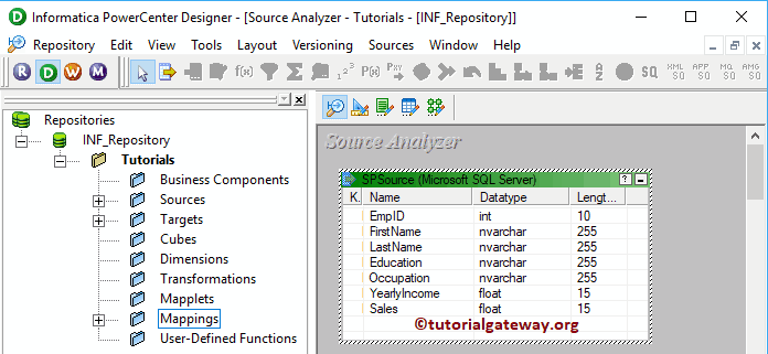
Please navigate to Target Designer to define the Target. In this example, we are using the existing SQL table (SP Destination) as our target definition. You can refer to Create Target Table to understand the process of creating a target definition

To create a new mapping, Please navigate to the Mappings menu in Menu Bar and select the Create.. option.
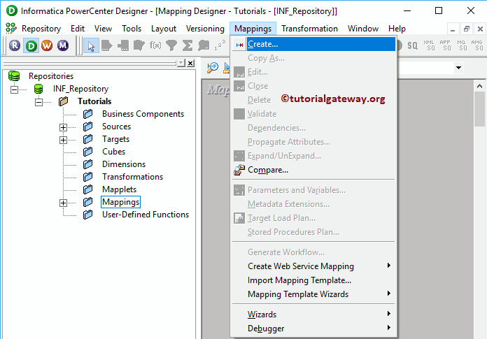
Once you select the Create.. option, a new Mapping Name window will be opened. Let me provide m_Transaction as the mapping name and click OK button.
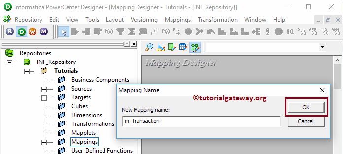
Drag and drop the SP Source from Sources folder to the mapping designer. Once you drag the source, Power Center Designer will automatically create the Source Qualifier Transformation (default transformation) for you.
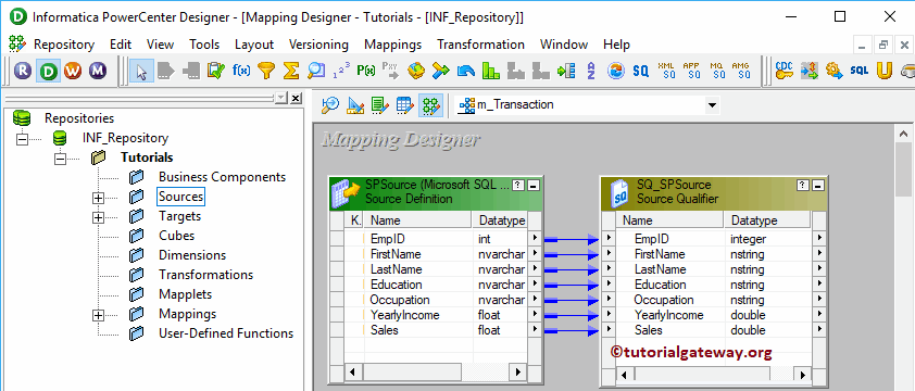
To create Transaction Control Transformation in Informatica, Please navigate to the Transformation menu in Menu Bar. Next, select the Create.. option

Selecting the Create.. option will open the Create Transformation window. Please select the Transaction Control Transformation from the drop-down list, and provide a unique name (Tran_Employee), and click on Create button
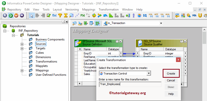
By clicking OK will create a Transaction Control Transformation for you.

Let me drag all the fields that are available in source definition to Transaction Control Transformation. Next, Drag and drop the target definition (SP Destination) from the Targets folder to the mapping designer. Lastly, connect the Transaction Control Transformation fields with the target definition using the Autolink.. option.

Double click on the Informatica Transaction Control Transformation to edit or configure the transformation. Please go to the Properties tab, and click on the Arrow beside the Transaction Control Condition to apply transactions at the mapping level.

Once you click the Arrow, an expression window will open. The Expression window in Transaction Control Transformation uses the IIF Function to test each row against the condition.
The Informatica Transaction Control Transformation provides the following built-in variables to apply transactions. For the demonstration purpose, let us take the above specified SP Source table and condition is EmpID = 5.
- TC_CONTINUE_TRANSACTION: This is the default value for this option. It does not perform any change for this row.
- TC_COMMIT_BEFORE: This is nothing but a Commit transaction in any relational database. If the condition is true, then it will first Commit the transaction. Next, it will begin a new transaction and writes the current row. Example: It will commit records up to EmpID 4 and start a new transaction to commit records from 5
- TC_COMMIT_AFTER: If the condition is true, then it will first write the current row and Commit the transaction. Next, it will begin a new transaction. Example: It will write and commit records up to EmpID 5 and begin a new transaction to commit records from 6
- TC_ROLLBACK_BEFORE: This is nothing a Rollback transaction in any relational database. If the condition is true, it will first Rollback the transaction. Next, it will begin a new transaction and writes the current row. Example: It will rollback records up to EmpID 4 and begin a new transaction to commit records from 5
- TC_ROLLBACK_AFTER: If the condition is true, it will first write the current row and then Rollback the transaction. Next, it will begin a new transaction. Example: It will rollback records up to EmpID 5 and begin a new transaction to commit records from 6
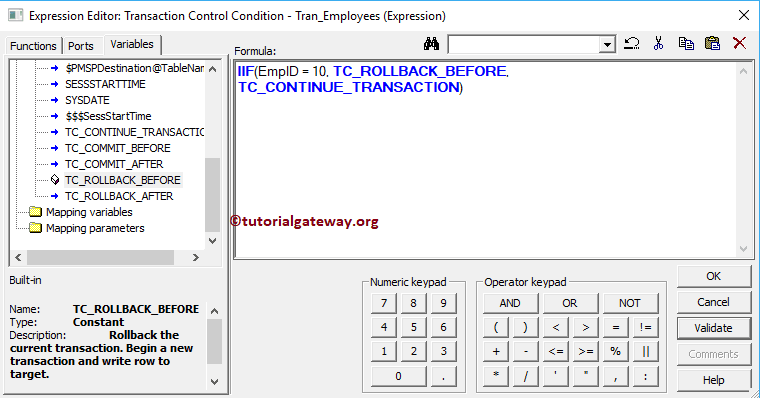
Click Apply and then click OK to close the Informatica Transaction Control Transformation window.

Before we close the Mapping, Let us Save, and Validate the mapping by going to Mapping Menu bar, and select the Validate option.
After you finish creating the Informatica Transaction Control Transformation Mapping, we have to create the Workflow for it. PowerCenter Workflow manager provides two approaches to create a workflow.
In this Informatica Transaction Control Transformation example, we will create the Workflow manually. To do so, Please navigate to Workflows Menu and select the Create option.

It will open the Create Workflow window. Please provide the unique name (wf_Transaction) and leave the default settings.

Once we created the workflow, our next step is to create a session task for our mapping.
There are two types of sessions:
For this Informatica Transaction Control Transformation example, we created a Non-reusable Session. To create Non-reusable Session, Please navigate to Tasks Menu and select the Create option as shown below.

Here, we are naming this session as s_Transaction. Once you click on the Create button, a new window called Mappings will open. Here, select the Mapping (m_Transaction) that you want to associate with this session.

Double click on the Session task will open the Edit Tasks window. Within the mappings tab, we have to configure the Source, Target Connections.
First, let us configure the source connections by clicking on the SQ_SPSource source present in the Sources folder. Within the Connections, click on the Arrow button beside the Relational type, and select the Database Object (Database Name) i.e., Source

Now, we have to configure the Target Connection. So, click on the SPDestination present in the Targets folder. Within the Connections, click on the Arrow button beside the Relational type, and select the Database Object (Target Database Name) i.e., target

Please change the Target Load Type to Normal or Bulk as per your requirements. Let me checkmark the Truncate target table option as well.
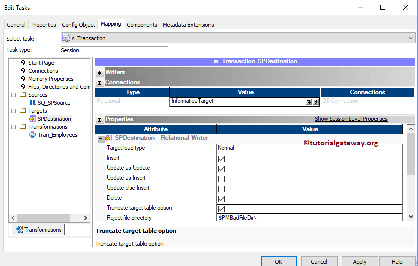
Next, navigate to Workflows Menu and select the Validate option to validate the Workflow.

Now, Let me start the Informatica Transaction Control Transformation Workflow. To do so, navigate to the Workflows menu and select the Start Workflow option.

Let us open the SQL Server Management Studio and write the following SQL Query to check whether we successfully transferred the data from a source or not. As you see that our target table is displaying records where EmpID = 10. Because Rollback will start before processing the record whose EmpID, is 10
This time we will use the TC_ROLLBACK_AFTER as the second argument in IIF. It means the Rollback option will perform after passing the EmpID 10.

As you can see, our target table is displaying records where EmpID is greater than 10

Union Transformation in Informatica
The Union Transformation in Informatica is used to combine data from multiple sources (excel files, flat file etc) or multiple SQL tables and produce one output to store in the target table. It is an active transformation and it is similar to the SQL Union All.
The Union Transformation in Informatica is very useful in real-time. For example, if the company has 100 stores and each store maintain their own sales data. End of the day they all belongs to one company and your job is to find out the one month or year sale for any single product. It is not practical to visit 100 stores or cross-checking 100 excel or flat files and calculating the sales.
In this situations, all you have to do is, use Union Transformation in Informatica to combine all the 100 excel files from 100 stores and store it in the data warehouse and then, calculate the product sales from the database.
Please remember the following guidelines while you are working with the Informatica Union Transformation :
- The Informatica Union Transformation allows multiple input groups but produce a single output.
- It doesn’t remove duplicate records from the input source.
- It doesn’t generate transactions.
- You can not use Sequence Generator Transformation to generate sequences
For this Informatica Union Transformation example, we are going to use the SQL tables that we created using the Router Transformation. The following screenshot will show you the data inside the [Router 1] table.

The data inside the [Router 2] table.

The data inside the [Router 3] table.

Here, Our task is to combine these three tables using the Informatica Union Transformation and save it in the destination table.
Before we start configuring the union transformation in Informatica, First connect to the Informatica repository service. In order to connect with the Repository service, we have to provide the Admin Console credentials. So, Please provide the appropriate Username and Password and click on Connect button as shown below.
TIP: Here you have to provide the Admin Username and password that you specified while installing the Server.

Once you connected successfully, Please navigate to Source Analyzer and define your Sources. In this Informatica union transformation example, we are using [Router 1], [Router 2], and [Router 3] tables from the SQL Server database as our source definitions. Please refer to Database Source to understand the steps involved in creating a source definition

Please navigate to Target Designer and define the Target. In this example, we are using the already created SQL table (Union Transformation) as our target definitions. Please refer Create Target table using Source Definition to understand the steps involved in creating a target definition

In order to create a new mapping, Please navigate to Mappings menu in Menu Bar and select the Create.. option. This will open the Mapping Name window as shown below. Here, you have to write a unique name for this mapping (m_Union_Transformation) and click OK button.

Next, Drag and drop the [Router 1], [Router 2], and [Router 3] source definitions from Sources folder to the mapping designer. Once you drag the source, the PowerCenter designer will automatically create the default transformation called source qualifier for them.
To create Union transformation in Informatica, Please navigate to Transformation menu in Menu Bar and select the Create.. option as we shown below.

Once you click on the Create.. option, Create Transformation window will be opened as shown below. Please select the Informatica Union Transformation from a drop-down list and specify the unique name (UN_Products) for this and click on Create button

Clicking the Create button will add the union transformation to the mapping designer. In order to perform union all, Union Transformation requires some data so, please connect the Router 1 Source qualifier with the transformation by dragging the required fields.
Once you drag the fields, the Informatica union transformation will create OUTPUT Group and New Group.

In order to merge more than one table, we need multiple groups like NEWGROUP. So, Double click on the Informatica Union transformation to create new groups. From the below screenshot you can see the list of available properties in the Transformation tab:
- Select Transformation: By default, it will select the transformation you clicked on.
- Rename: This button will help you to rename the union transformation to a more meaningful name.
- Make Reusable: If you check mark this option then, this transformation will become reusable transformation.
- Description: Please provide a valid description of this transformation.

Within the Groups tab, we have to define the group names. Please click on the New Group button (beside the close button) to add a new group and change the names as per your requirements.
By clicking the close button you can delete the unwanted groups. From the below screenshot you can observe that we created three groups Least Sales, Medium Sales and Highest Sales.

Once you finish creating the Groups, Click OK to close the transformation window.

Next, w have to assign the Source Qualifiers to the new groups that we created earlier. so, please connect the Router 2 Source qualifier with the Medium Sales and Router 3 Source qualifier with the Highest Sales

Next, Drag and drop the target definition (Union Transformation) from Targets folder to the mapping designer and connect the Transformation with the target definition. Please use the Autolink.. option to connect them.

Before we close the Mapping, Let us validate the mapping by going to Mapping Menu bar and selecting the Validate option.
Once we finish creating the Mapping we have to create the workflow for it. PowerCenter Workflow manager provides two approaches to create a workflow.
In this Informatica Union Transformation example, we will create the Workflow manually. In order to create a new Workflow, Please navigate to Workflows Menu and select the Create option. This will open Create Workflow window. Please provide the unique name (wf_Union_Transformation) and leave the default settings.

Once we created the workflow, our next step is to create a session task for our mapping.
There are two types of sessions:
For this Informatica Union Transformation example, we are going to create Non-reusable Session. Please navigate to Tasks Menu and select the Create option to open the Create Task window. Here you have to select the Session as Task type (default) and enter a unique name (S_Union_Transformation) for the session.
Once you click on the Create button, a new window called Mappings opened. Here you have to select the mapping you want to associate with this session. From the below screenshot, you can observe that we are selecting the mapping (m_Union_Transformation) that we created earlier (in Step 3).

Double click on the Session Task to configure it. Although we have to configure Sources, targets, and some common properties, we are explaining only a few properties. We strictly recommend visiting the Session article to understand the remaining properties.
From the below screenshot you can observe that we assigned the $target variable to Connection Value, we check marked the Truncate target table option to truncate the existing data from the destination table.

From the below screenshot you can observe that the Informatica Union Transformation workflow is a valid one. Now, Let us start the Workflow by navigating to Workflows menu and selecting the Start Workflow option.

Once you select the Start Workflow option, the PowerCenter Workflow monitor will be opened to monitor the workflow. From the below screenshot, you can observe that our workflow is executed without any errors.

Let us open the SQL Server Management Studio to check whether we successfully combined the records present in Router 1, Router 2, and Router 3 tables or not. Please refer to SQL Union All article.

Update Strategy Transformation in Informatica
The Update Strategy Transformation in Informatica is an Active and Connected transformation. It is useful to update, insert, or delete the records in a target based on source table data. And the beauty of this transformation is: you can restrict the records from not reaching into the target table.
This article explains how to configure Informatica Update Strategy Transformation. Or, the steps involved in configuring the Update Strategy to update the records in the target table.
For this Informatica Update Strategy Transformation example, we are going to use the below show data (Customer Record table)

And the destination table is:

If you compare the Source table with the destination table, there are multiple changes in Email Address and Professional columns. In this example, our task is to use the Informatica Update Strategy Transformation to update the changes in the destination table.
Before we start configuring the Informatica Update Strategy Transformation, First let me connect with the repository service. To do so, enter the Admin Console username and password you specified while installing the Server.
Once you connected successfully, Please navigate to Source Analyzer and define your Sources. In this example, we are using the [Customer Record] table from the SQL Server database as our source definitions. Please refer Database Source article

Please navigate to Target Designer and define the Informatica Update Strategy Transformation Target. In this example, we are using the already created SQL table (DupCust) as our target definition. Please refer Create Target table using Source Definition to understand the steps involved in creating a target definition

To create a new mapping, Please navigate to Mappings menu in Menu Bar, and select the Create.. option.

It opens the Mapping Name window to write a unique name for this mapping. Let me write m_update_trans and click the OK button.

Drag and drop the Customer record source definitions from Sources folder to the mapping designer. Once you drag the source, the Power Center designer automatically creates the Source Qualifier Transformation for you.

To create Update Strategy Transformation in Informatica, Please navigate to the Transformation menu and select the Create.. option.

Once you click on the Create.. option, Create Transformation window will open. Please select the Update Strategy Transformation from the drop-down list. Next, specify the unique name (ups_Customers) and then click on Create button

Once you click on the Create button, Update Strategy Transformation added to the mapping designer.

Next, Drag and drop the target definition (DupCust) from Targets folder to the mapping designer

In this example, we want to update the changes that happened in Email Address and Professional Columns. So, drag those two fields along with Key column to the Update Strategy Transformation in Informatica

Double click on the Informatica Update Strategy Transformation to configure it. From the below screenshot, you can see the list of available properties in the Update Strategy Transformation tab:
- Select Transformation: By default, it will select the transformation you clicked on.
- Rename: This button will help you to rename the Update Strategy Transformation to a more meaningful name.
- Make Reusable: If you checkmark this option, this transformation will become a reusable transformation.
- Description: Please provide a valid description.

The below screenshot shows the list of available options in the Informatica Update Strategy Transformation Ports tab:
- Port Name: List of available column names inside this Informatica Update Strategy. By clicking the New column button, you can add new columns, and by clicking the scissors button, you can delete the unwanted columns.
- I: Columns that are check-marked under this section are Input columns.
- O: Columns that are check-marked under this section are Output columns. If you unchecked any column, that column would not be available to load it in the target table.

Under the Informatica Update Strategy Transformation properties tab, we had:
- Update Strategy Expression: Here you have to specify whether you want to perform Insert, Delete, or an Update
- DD_INSERT: Numeric Value is 0. Used to insert records.
- DD_UPDATE: This is used to update rows, and the Numeric Value is 1.
- DD_DELETE: Numeric Value is 2. Used to delete rows.
- DD_REJECT: Numeric Value is 3. Used to reject rows.
- Forward Rejected Row: If you want to forward the rejected rows to the next transformation, then you have to checkmark this option.
- Tracing Level: Keep this to default Normal.

It will open the Expression Editor to write a custom expression. Here, we are using the DD_UPDATE expression

Click Apply and click OK to close the window.

Next, connect the Informatica Update Strategy transformation with the target definition using the Autolink.. option.

Before we close the Mapping, Let us validate the Informatica Update Strategy Transformation mapping by going to Mapping and chose the Validate option.
After we finish creating the Mapping, we have to create a workflow for it. It provides two approaches to creating a workflow.
In this Informatica Update Strategy Transformation example, we will create the Workflow manually. So, navigate to Workflows Menu and select the Create option.

It opens the Create Workflow window. Please provide the unique name (wf_update_tran) and leave the default settings.

Once we created the Informatica Update Strategy workflow, our next step is to create a session task for our mapping.
There are two types of sessions:
For this Informatica Update Strategy Transformation example, we will create a Non-reusable Session. For this, go to Tasks Menu and select the Create option.

Please provide a unique name (s_update_tran) for this session. Once you click on the Create button, a new window called Mappings will open. Here, we are selecting the m_update_trans

Please link the Start Task with a newly created session task

Double click on the Session task will open the Edit Tasks window. Within Properties Tab
Treat Source Rows as: By default, Data-Driven is selected in this case. If not, please change it to Data-Driven. Remember, the Data-Driven option means, instead of performing default insertion, it will use the Update Strategy Transformation option to load the target table.

$Source connection value: This property will store the relational source information in the $Source variable. So, click on the Arrow we marked below, and select the SQL Tutorial as the source information.

$Target connection value: This property will store the relational target information in the $Target variable. So, click on the Arrow we marked below, and select the SQL Test target as the Target information.

Within the mappings tab, we have to configure the Source, target Connections. First, let us configure the source connections by clicking on the SQ_CustomerRecord source present in the Sources folder.
Within the Connections, click on the Arrow button beside the Relational type, and use the Connection variable that we created in our previous step, i.e., $Source

Now, we have to configure the Target Connection. So, click on the DupCust present in the Targets folder. Within the Connections, click on the Arrow button beside the Relational type, and use the Connection variable $Target

Next, Let me start the Informatica Update Strategy Transformation Workflow. To do so, navigate to the Workflows menu and select the Start Workflow option.
Let us open the SQL Server Management Studio to check whether we successfully performed the Informatica update strategy.

Informatica Update Strategy using Session Properties
In this article, we are going to explain, How to achieve Informatica Update Strategy using Session Properties. Or, the steps involved in configuring the Session Properties to achieve the Update Strategy without using any Update Strategy Transformation with an example.
In Informatica, you can use the Session Properties to achieve the update strategy. But, this approach is one of the worst approaches in real-time. Because, instead of Lookup this will blindly update existing records (even there is no change), or insert each and every record. This approach is fine for the small table.
For this example, we are going to use the below show data (Employee Duplicate table)

And the destination table is:

As you can that the destination table has 1 record and two extra columns. These extra columns will help you to understand the problems you might face in this approach.
Before we start configuring the Session Properties, First let me connect with the Informatica repository service. In order to do so, we have to provide the Admin Console credentials. So, Please provide the appropriate Username and Password, and click the Connect button.
TIP: Here you have to provide the Admin Username and password that you specified while installing the Server.
Step 1: Create a Source Definition
Once you connected successfully, Please navigate to Source Analyzer and define your Sources. In this example, we are using [Employee Duplicate] table from SQL Server database as our source definitions. Please refer Database Source to understand the steps involved in creating a source definition

Step 2: Create Target Definition
Please navigate to Target Designer and define the Target. In this example, we are using the already created SQL table (Employee Dup) as our target definition. Please refer Create Target table using Source Definition to understand the steps involved in creating a target definition

Step 3: Create a Mapping
To create a new mapping, Please navigate to Mappings menu in Menu Bar, and select the Create.. option.

This will open the Mapping Name window to write a unique name for this mapping. Let me write m_update_with_session and click OK button.
TIP: Please refer Mapping article to understand the procedure to create Mapping

Drag and drop the Employee Duplicate source definitions from Sources folder to the mapping designer. Once you drag the source, Power Center designer will automatically create the source qualifier for you. I suggest you refer the Source Qualifier Transformation article.
Next, create an Expression Transformation, and Drag all the fields from Source Qualifier to Expression Transformation. I Suggest you refer Expression Transformation article for better understanding.

Double click on the Expression transformation to add new fields, or write to custom expressions. From the below screenshot you can observe that We added 2 new columns using the New Port button. We are going to use these new columns to store the Created Date and Modified Date

Let us write the custom expression. To do this, Click on the arrow button beside the CreatedOn.
TIP: All these new columns are output ports. So, please check mark O

This will open the Expression Editor to write a custom expression. Here, we want the system date so, write SYSDATE.

From the below screenshot you can observe that We did the same for the UpdatedOn column

Next, Drag and drop the target definition from Targets folder to the mapping designer, and connected the Expression transformation with the target definition. Please use the Autolink.. option to connect them.

Before we close the Mapping, Let us validate the mapping by going to Mapping Menu bar and selecting the Validate option.
Step 4: Create a Workflow
After we finish creating the Mapping, we have to create a workflow for it. Power Center Workflow manager provides two approaches to create a workflow.
In this example, we will create the Workflow manually. To do so, Please navigate to Workflows Menu and select the Create option.

This will open Create Workflow window as shown below. Please provide the unique name (wf_update_using_session) and leave the default settings.

Once we created the workflow, our next step is to create a session task for our mapping.
Step 4(a): Create a Session
There are two types of sessions:
For this example, we will create a Non-reusable Session. In order to create the same, Please navigate to Tasks Menu and select the Create option as shown below.

Please provide a unique name for this session. Here, we are naming it as s_update_using_session. Once you click on the Create button, a new window called Mappings will be opened. Here, we are selecting the m_update_with_session

Double click on the Session task will open the Edit Tasks window. Within Properties Tab
$Source connection value: This property will store the relational source information in $Source variable. So, click on the Arrow we marked below, and select the SQL Tutorial as the source information.

$Target connection value: This property will store the relational target information in $Target variable. So, click on the Arrow we marked below, and select the SQL Test target as the Target information.

Treat Source Rows as: Change the default Insert to Update. It means, instead of performing the only insertion, it will perform update too.

Within the mappings tab, we have to configure the Source, target Connections. First, let us configure the source connections by clicking on the SQ_EmployeeDuplicate source present in the Sources folder.
Within the Connections, click on the Arrow button beside the Relational type, and use the Connection variable that we created in our previous step i.e., $Source

Now, we have to configure the Target Connection. So, click on the EmployeeDup present in the Targets folder. Within the Connections, click on the Arrow button beside the Relational type, and use the Connection variable $Target

Next, checkmark the Update else Insert.
Update else Insert: If the records already exist then it will perform UPDATE on that records. And, if the records do not exist then it will perform INSERT

Please link the Start Task and the session task.

Next, navigate to Workflows Menu and select the Validate option to validate the Workflow. Now, Let me start the Workflow. To do so, navigate to the Workflows menu, and select the Start Workflow option.
Once you select the Start Workflow option, the PowerCenter Workflow monitor will be opened to monitor the workflow. From the below screenshot you can observe that our workflow is executed without any errors.

Let us open the SQL Server Management Studio to check whether we successfully performed the update strategy. If you look at the first record, this record is updated along with the insertion. In a simple language, we can say, this approach is simply replacing all the existing target table records with the source table records.

Let me update Yearly Income for EmpID 3 and add one more record.

From the below screenshot you can observe that our workflow is executed without any errors.

As you can see, again all the records are inserted freshly.

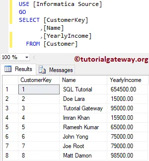
And the destination table is:

In our previous article, we already explained the Update Strategy Transformation. In this example, we will show you another way of using this Informatica Update Strategy Transformation.
First, let me connect with the repository service. To do so, enter the Admin Console username and password you specified while installing the Server.
Once you connected successfully, Please navigate to Source Analyzer and define your Sources. In this Informatica Update Strategy example, we are using the Customer table from the SQL Server database as our source definitions. Please refer Database Source article.

Please navigate to Target Designer and define the Informatica Update Strategy Target. In this example, we are using the already created SQL table (New Customers) as our target definition. Please refer Create Target table using Source Definition to understand the target definition

To create a new Informatica Update Strategy mapping, Please navigate to the Mappings menu and select the Create.. option.

It opens the Mapping Name window to write a unique name (m_update_Cust) for this mapping and click OK button.

Drag and drop the Customer record source definitions from Sources folder to the mapping designer. Once you drag the source, the Power Center designer will automatically create the Source Qualifier for you.
To create a Lookup Transformation, Please navigate to the Transformation menu and select the Create.. option.

Once you click on the Create.. option, Create Transformation window will open. Please select the Lookup Transformation from the drop-down list and specify the unique name (lkp_Cust) and click on Create button

Once you click on the Create.. button, a Select Lookup Table for Lookup Transformation window will open. Here, we want to use the Target table as the lookup source.
TIP: If your lookup table is present in Source, then select Source. Here, you can also Import from an external source.

Clicking the Create button adds the Lookup Transformation to the mapping designer. Next, drag and drop the Customer key from Source Qualifier.

Double click on the lookup transformation to configure its settings. The below screenshot will show you the list of available options in the Ports tab. From the below screenshot, you can observe that We changed the Input port name (CustomerKey_lkp).

Within the Properties section, we changed the Lookup Policy on Multiple Match to Use First value.

Within the condition tab, we added one condition CustmerKey = CustmerKey_lkp. The below condition states that Lookup transformation will check the lookup input source (i.e., Customer Key) is equal to existing Customer Key or Not.

To create an Expression Transformation, select the Create.. option from the Transformation menu. As you can see, we assigned the name as Exp_Cust

Now let me add all the fields from Source Qualifier to Expression Transformation and the Key column from Lookup Transformation.

As you can see, we changed the column name (column added from lookup). Next, we would like to add one Flag field using New Column button

For this flag field, let me write an expression by clicking the Arrow. Remember, If you want to perform Delete or some other operation based on some condition, then use multiple Tags.

Here, the ISNULL is to check whether it is Null or not
Below the specified expression check whether the Customer key column coming from the lookup field is Empty or not. If it is empty, one will return otherwise 0. And the expression is IIF(ISNULL(CustomerKey_lkp), 1, 0). Please refer to IIF to understand the syntax of an IIF.

Click OK to Apply the setting

Please refer to Router Transformation article to understand the steps involved in creating it.

Once you created it, Please connect the Expression Transformation with the router transformation by dragging the required fields. From the below screenshot, you can observe that we are adding all the fields except the lookup column field.

Double click on the Router transformation to add Groups. Use Add New Group button to add required groups

From the below screenshot, you can observe that we created one group for Inserting New Records and another for Updating existing records.

Let us provide the expression or condition for the First group by clicking the arrow button. It opens the Expression Editor to write a custom expression. Here, we want the Customers whose Customer key is Null which means, non-existing records

For Update group, we have written the expression as Flag = 0 which means, all the existing records

Once you finish configuring the properties, Click OK to close the transformation window.

Please refer to Update Strategy Transformation in Informatica to understand the steps involved in creating it. Let me add two Update Strategies:
- Insert_Cust: This is for inserting New records into a target table.
- Update_Cust: This is to update existing records in a target table.

Drag the fields from Insert group (Flag = 1) to Insert_Cust and drag fields from Update group (Flag = 0) to Update_Cust
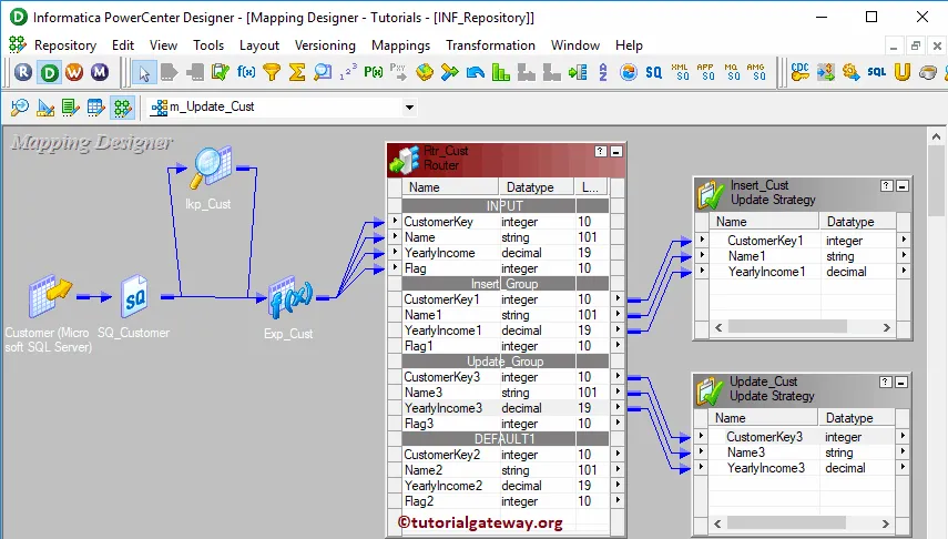
Double click on the Insert_Cust Update Strategy to configure it. Let me change the Update Strategy Expression to 0 or DD_INSERT

Double click on the Update_Cust Update Strategy to configure it. Let me change the Update Strategy Expression to 1 or DD_UPDATE for an update

Next, Drag and drop the target definition from the Targets folder to the mapping designer. Repeat the same for one more time and Auto link fields.
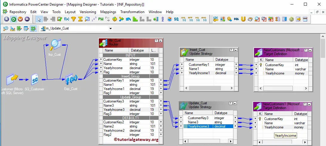
Before we close the Mapping, Let us validate the mapping by going to Mapping Menu bar and selecting the Validate option.
After we finish creating the Informatica Update Strategy Mapping, we have to create a workflow for it. Power Center Workflow manager provides two ways to create a workflow.
In this example, we will create the Workflow manually. To do so, Please navigate to Workflows Menu and select the Create option.
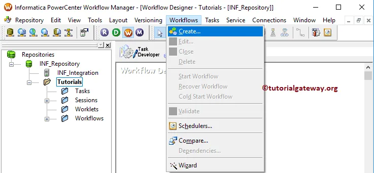
It opens the Create Workflow window. Provide a unique name (wf_Customers) and leave the default settings.
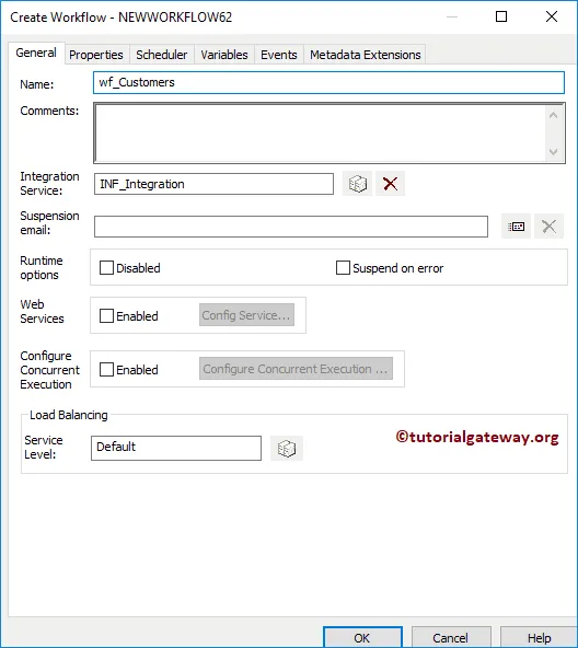
Once we created the workflow, our next step is to create a session task for our mapping.
There are two types of sessions:
For this Informatica Update Strategy example, we will create a Non-reusable Session. Select the Create option from Tasks Menu
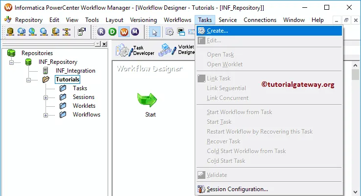
Please provide a unique name for this session (s_Customers). Once you click on the Create button, a new window called Mappings will open. Here, we are selecting the m_update_Cust

Double click on the Session task will open the Edit Tasks window. Within Properties Tab
$Source connection value: This property will store the relational source information in the $Source variable. So, click on the Arrow we marked below, and select the Source as the source information.

$Target connection value: This property will store the relational target information in the $Target variable. So, click on the Arrow we marked below, and select the below Target as the Target information.

Within the Mappings tab, we have to configure the Source and Target Connections for Informatica Update Strategy. First, let us configure the source connections by clicking on the SQ_Customer source present in the Sources folder.
Within the Connections, click on the Arrow button beside the Relational type, and use the Connection variable that we created before, i.e., $Source

Now, we have to configure the Target Connection. So, click on the NewCustomers present in the Targets folder. Within the Connections, click on the Arrow button beside the Relational type, and use the Connection variable $Target. Repeat the same for NewCustomers1

Next, Let me start the Informatica Update Strategy Workflow. To do so, navigate to the Workflows menu and select the Start Workflow option.

Let us open the SQL Server Management Studio to verify whether we successfully performed the update strategy or not.

XML Generator Transformation in Informatica
The XML Generator Transformation in Informatica is an Active and Connected transformation. This transformation is useful in generating XML files inside a pipeline.
In this article, we will show you how to use XML Generator Transformation in Informatica to generate an XML file from the Database table with an example.
For this Informatica XML Generator Transformation example, we are going to use the below show data (Customer record table)

Let’s see how to use this XML Generator Transformation in Informatica to generate an XML file using the SQL Database table. Before we start configuring, First, let me connect with the repository service.
To do so, we have to provide the Admin Console credentials. So, Please provide the appropriate Username and Password, and click the Connect button.
TIP: Here, you have to provide the Informatica Admin Username and password that you specified while installing the Server.
Once you connected successfully, please navigate to Source Analyzer and define your Sources. In this example, we are using the Customer table from the SQL Server database as our source definitions. Please refer Database Source to understand the steps involved in creating source definition

First Approach – Please navigate to Target Designer to define the Informatica XML Generator Transformation Target. In this example, our task is to create an XML File. So, go to the Targets menu and select the Import XML Definition option. By this, you can define the XML Definition inside a Target definition.

Ideal Approach – Go to Targets menu and select the Create option.

Once you select the Create option, a new window called Create Target table will be displayed as shown below. Please provide a unique name for the target, and select the database type as Flat File.
Once you complete, Please click on the Create button to create a new empty table in our PowerCenter Target Designer.

Double-click on the newly created target table. Next, go to the Columns Tab to add a new column. Please select the first button (before the scissors symbol). It opens the empty row to add Column Name, Data Type
From the below screenshot, you can observe that we added one XML_Output column of a string data type.

Now you can see the target table with one column name. It is the column that handles the XML file.

To create a new mapping for Informatica XML Generator Transformation, Please navigate to Mappings menu in Menu Bar, and select the Create.. option.

It will open the Mapping Name window to write a unique name for this Mapping. Let me write m_xml_generator and click OK button.
TIP: Please refer Mapping article to understand the procedure to create Mapping

Drag and drop the Customer record source definitions from Sources folder to the mapping designer. Once you drag the Source, the Power Center designer will automatically create the source qualifier for you. I suggest you refer to the Source Qualifier Transformation article.
To create an XML generator Transformation, Please navigate to the Transformation menu in Menu Bar and select the Create.. option.

Once you click on the Create.. option, Create transformation window opened. Please select the XML Generator Transformation from the drop-down list and specify the unique name (XML_GenCustomer) and click on Create button

Once you click on the Create.. button, a new window called Import XML Definition will be opened as shown below. Here, you have to specify the XSD or XML definition for this XML file.
Local File: If the XSD file is in the local file system, then select this option.

URL: Select the XML definition file at particular URL

Non-XML Targets: If the source is a Non-XML file, and if it is present in the Target definition

Non-XML Sources: If you don’t have an XSD file and want to use the SQL table in the Source definition, then select this option. For this example, we are going to use the Customerrecord table present in the Source definition.

Click Open

Click No

It will open an XML wizard. Click Next button

Every XML file has to be processed using a Valid XML Definition (or XSD). Please define the XML definition in the second page. In this example, we want to save our XML file using Entity relation. So, we are selecting the first option.

Once you click on the Finish button, XML Generator Transformation added to the mapping designer.

Now let me add all the fields from Source Qualifier to XML Generator Transformation

Next, Drag and drop the target definition from the Targets folder to the mapping designer. Next, connect the XML Generator Transformation data output to the XML_Output field in the Target table.

Before we close the Mapping, Let us Save, and Validate the mapping by going to Mapping Menu bar, and select the Validate option.
After we finish creating the Mapping, we have to create the workflow for it. Power Center Workflow manager provides two approaches to create a workflow.
In this Informatica XML Generator Transformation example, we will create the Workflow manually. To do so, Please navigate to Workflows Menu and select the Create option.

It will open the Create Workflow window. Please provide the unique name (wf_XMLGenerator) and leave the default

Once we created the workflow, our next step is to create a session task for our mapping.
There are two types of sessions:
For this Informatica XML Generator Transformation example, we created a Non-reusable Session. To create Non-reusable Session, Please navigate to Tasks Menu and select the Create option.

Please provide a unique name for this session. Here, we are naming it as s_XMLGenerator. Once you click on the Create button, a new window called Mappings opened.
Here you have to select the mapping that you want to associate with this session i.e., m_xml_generator.

Double click on the Session task will open the Edit Tasks window. Within the Mappings tab, we have to configure the Source, and Target Connections. First, let us configure the source connections by clicking on the SQ_CustomerRecord source present in the Sources folder.
Within the Connections, click on the Arrow button beside the Relational type, and select the source table database (Source)

Now you can see the Source as the relational connection

Now, we have to configure the Target Connection. So, let us configure the target connection by clicking on the XMLCustomer_Records in the Targets folder.
- Output File Directly: It will use the default directory, but you can change the directory by giving the full path.
- Output filename: Please change the extension to XML

You can use the Transformation properties to Validate or Format the Output (generated XML) file

Next, navigate to Workflows Menu and select the Validate option to validate the Workflow.

Now, Let me start the Informatica XML Generator Transformation Workflow by selecting the Start Workflow option in Workflows Menu.

Let us open the default target location of the Informatica to check whether we successfully created an XML file from the source table or not.

You can see the data inside the xmlcustomer_records xml file.

XML Parser Transformation in Informatica
The XML Parser Transformation in Informatica is an Active and Connected transformation. This transformation is useful to extract XML data from files inside a pipeline.
In this article, we will show you how to use XML Parser Transformation in Informatica to extract data from an XML file and load it into the Database table with an example.
For this Informatica XML Parser Transformation example, we are going to use the below show XML file

XSD that we are going to use is:

And the Destination table is Customer Record. As you can see, it is an Empty table

In this article, we will show you how to use this XML Parser Transformation in Informatica to read XML data from the CSV file to the SQL Database table.
Before we start configuring, First, let me connect with the Informatica repository service. To do so, we have to provide the Admin Console credentials. So, Please provide the appropriate Username and Password, and click the Connect button.
TIP: Here you have to provide the Admin Username and password that you specified while installing the Server.
Once you connected successfully, Please navigate to Source Analyzer to define your Sources. As we said before, we are using the XML file present in the local File System as our source definitions. So, Please navigate to Source menu, and select the Import from File.. option

Once you choose the Import from File.. option, a new window called Open Flat File will open. Please select the XMLCustomers.csv file from your local file system and click the Open button. I suggest you refer Flat File Source article to under the following steps.

Once you click the Open button, a new pop up window called Flat File Import Wizard will open.

Within Step 2: Under Delimiter section, please select the delimiter

Here, we can edit the Column Name, Data type, Length or Precision, Scale, and Width. In general, we don’t do that, but if you want, you can do it.

From the below screenshot you can observe that we can see our newly created Flat File source.

Please navigate to Target Designer to define the Target for Informatica XML Parser Transformation. In this example, we are using the existing SQL table (Customer Record) as our target definition. You can refer to Create Target table using Source Definition to understand the process of creating a target definition

To create a new mapping, Please navigate to Mappings menu in Menu Bar, and select the Create.. option.

It will open the Mapping Name window to write a unique name for this Mapping. Let me write m_XMLParser and click OK button.
TIP: Please refer Mapping article to understand the procedure to create Mapping

Drag and drop the XML Customers flat file from Sources folder to the mapping designer. Once you drag the source, the Power Center designer will automatically create the source qualifier for you. I suggest you refer to the Source Qualifier Transformation article.
To create XML Parser Transformation, Please navigate to the Transformation menu in Menu Bar and select the Create.. option.

Once you click on the Create.. option, Create Transformation window will open. Please select the XML Parser Transformation from the drop-down list and specify the unique name (XML_ParseCustomer) and click on Create button

Once you click on the Create.. button, a new window called Import XML Definition will be opened as shown below. Here, you have to specify the XSD or XML definition for this XML file.
- Local File: If the file is a local file system, then select this option.
- URL: Select the file at particular URL
- Non-XML Sources: If the source is a Non-XML file (SQL table) and if it is present in the Informatica Source definition.
- Non-XML Targets: If the source is a Non-XML file, and if it is present in the Informatica Target definition
Please select the CustomerXSD.xml file from your local file system and click the Open button.

Click Yes or No as per your requirement

If you select Yes from the above screenshot then the following window opens. Change XML Views Creation and naming Option will be displayed. Please change the options as per your requirements.

It will open an XML wizard. Click Next button

Every XML file has to be processed using a Valid XML Definition (or XSD). Please define the XML definition in the second page.
In this example, we are using the Entity relation XSD. So, we are selecting the first option.

Once you click on the Finish button, XML Parser Transformation in Informatica workspace added to the mapping designer.

First, let me add the XML field from Source Qualifier to XML Parser Transformation. Next, Drag and drop the target definition from the Targets folder to the mapping designer.

Next, connect the XML Parser Transformation fields to the Customer record Target table.

After we finish creating the Mapping, we have to create the workflow for it. Power Center Workflow manager provides two approaches to create a workflow.
In this Informatica XML Parser Transformation example, we will create the Workflow manually. To do so, Please navigate to Workflows Menu and select the Create option.

It will open the Create Workflow window. Please provide the unique name () and leave the default settings.

Once we created the workflow, our next step is to create a session task for our mapping.
There are two types of sessions:
For this Informatica XML Parser Transformation example, we created a Non-reusable Session. To create Non-reusable Session, Please navigate to Tasks Menu and select the Create option.

Please provide a unique name for this session. Here, we are naming it as s_XMLParseCustomer. Once you click on the Create button, a new window called Mappings opened. Here you have to select the Mapping that you want to associate with this session, i.e., m_XMLParser.

Double click on the Session task will open the Edit Tasks window. Within the mappings tab, we have to configure the Source and Target Connections. First, let us set the Source connection by clicking on the SQ_XMLCustomers present in the Sources folder.
- Source File directory: It will use the default directory, but you can change the directory by giving the full path. For example, D:\File Examples\
- Source filename: It will automatically detect. If not, please specify the file name along with the extension.

Next, we have to configure the target connection. So, select the CustomerRecord under the targets folder.
Within the Connections, click on the Arrow button beside the Relational type, and select the target table database (Target)

Change the Target Load type based on your requirement

Next, navigate to Workflows Menu and select the Validate option to validate the Workflow.

Now, Let me start the Informatica XML Parser Transformation Workflow. To do so, navigate to the Workflows menu and select the Start Workflow option.

Let’s open the SQL Server Management Studio and write following SQL Query to check whether we successfully transfered XML data into the table or not.

XML Source Qualifier in Informatica
The XML Source Qualifier in Informatica is an Active and Connected transformation. While reading the XML Source definition, this is the default transformation generated by the Power Center Designer.
Informatica XML Source Qualifier transformation determines how the Power Center reads the source data. Remember, XML Source Qualifier always has one input port or one output port.
For this Informatica XML Source Qualifier Transformation example, we use the below XML and Load Data to SQL Server.
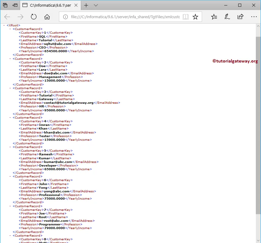
Before we start configuring the Informatica XML Source Qualifier, First, let me connect with the Informatica repository service.
To do so, we have to provide the Admin Console credentials. So, Please provide the appropriate Username and Password specified while installing it and click the Connect button.
Please navigate to Source Analyzer to define your Sources. As we said before, we are using the XML file present in the local File System as our source definitions. So, Please navigate to Source menu and select the Import XML Definition.. option as shown below

Once you choose the Import XML Definition.. option, a new window called Import XML Definition opened. We have already explained these option in XML Parser Transformation.

Please select the xmlcustomer_records.xml file from your local file system.

Click No

It opens an XML wizard. Click Next button

Every XML file has to be processed using a Valid XML Definition (or XSD). Please define the XML definition in the second page.
In this example, we are using the XML file with Entity relation so, we are selecting the first option. If you are using an XML file Hierarchies, then select the second option, etc.

From the below screenshot you can observe that, you can see our newly created XML Source definition in Informatica

Please navigate to Target Designer to define the Target. In this example, we are using the existing SQL table (XMLCustomers) as our target definition. You can refer to Create a Target table using Source Definition to understand the process of creating a target definition
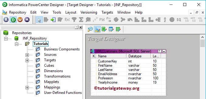
To create a new mapping for XML source qualifier transformation in Informatica, Please navigate to the Mappings menu in Menu Bar and select the Create.. option.

Once you select the Create.. option, a new Mapping Name window will open. Let me provide m_XMLSource as the mapping name and click OK button.
TIP: Please refer Mapping article to understand the procedure to create Mapping

Drag and drop the XML source definition (xmlcustomer_records) from the Sources folder to the mapping designer. Once you drag the source, the Power Center designer automatically creates the XML source qualifier transformation for you.

Let me remove the XML Source Qualifier
To explicitly create XML Source Qualifier in Informatica, Please navigate to the Transformation menu in Menu Bar. Next, select the Create.. option

Selecting the Create.. option will open the Create Transformation window. Please select the XML Source Qualifier Transformation from the drop-down list and provide the unique name (XMLCustomers_SQ) for this transformation and click on Create button

That opens the Select Sources for Source Qualifier Transformation window. Click OK to select the xmlcustomer_records as the source.
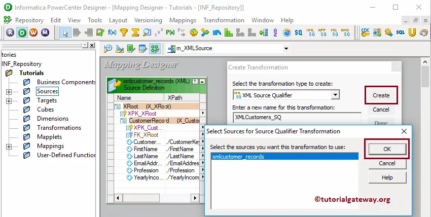
Now you can see the same image that you have seen before
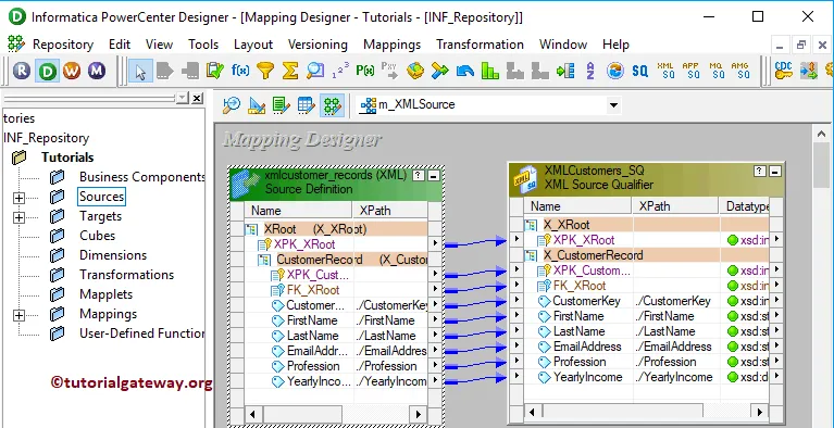
Double click on the XML Source Qualifier transformation to witness and alter the properties. Below screenshot shows you the list of available properties in the Transformation tab:
- Select Transformation: By default, it will select the transformation you chose (or clicked on).
- Rename: This button helps you to rename the XML Source Qualifier transformation name.
- Description: Use this space to provide a valid description of this transformation.
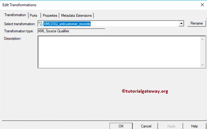
Below screenshot show you the available options in the Ports tab:
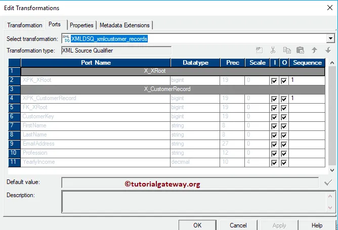
Next, Drag and drop the target definition (XMLCustomers) from the Targets folder to the mapping designer. Next, connect the XML source qualifier Transformation with the target definition. Please use the Autolink.. option to connect them.
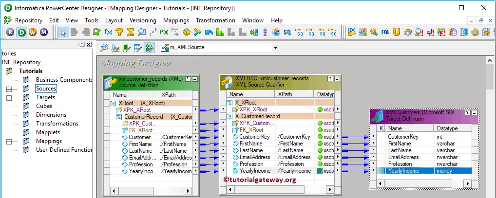
Before we close the Mapping, Let us Save, and Validate the mapping by going to Mapping Menu bar, and select the Validate option.
After you finish creating the Mapping, we have to create the workflow for it. Power Center Workflow manager provides two approaches to create a workflow.
In this example, we will create the Workflow manually. To do so, Please navigate to Workflows Menu and select the Create option.
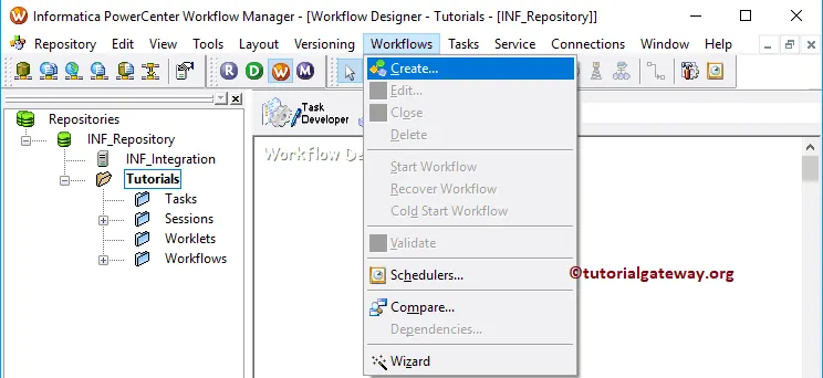
It will open the Create Workflow window as shown below. Please provide the unique name (wf_XMLSource) and leave the default settings.
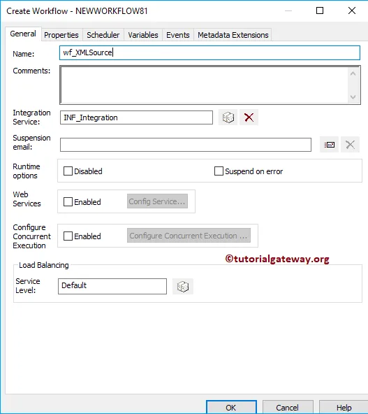
Once we created the workflow, our next step is to create a session task for our mapping.
There are two types of sessions:
For this example, we created a Non-reusable Session. To create Non-reusable Session, Please navigate to Tasks Menu and select the Create option as shown below.

Please provide a unique name for this session. Here, we are naming it as s_XMLSource. Once you click on the Create button, a new window called Mappings will open. Here you have to select the Mapping that you want to associate with this session, i.e., m_XMLSource.
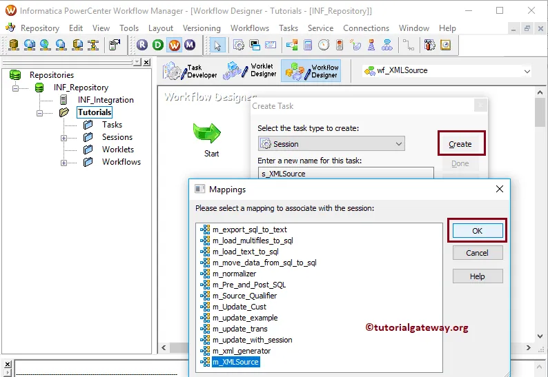
Double click on the Session task will open the Edit Tasks window. Within the mappings tab, we have to configure the Source and Target Connections. First, let us configure the Source connection by clicking on the XMLSQ_xmlcustomer_records present in the Sources folder.
- Source File directory: It will use the default directory, but you can change the directory by giving the full path. For example, D:\File Examples
- Source filename: It will automatically detect. If not, please specify the file name along with the extension.
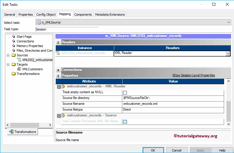
Next, we have to configure the target connection. So, select the XMLCustomers under the targets folder. Within the Connections, click on the Arrow button beside the Relational type, and select the target table database (Target)
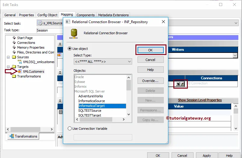
Next, navigate to Workflows Menu and select the Validate option to validate the Workflow.

Now, Let me start the XML source qualifier transformation Workflow by selecting the Start Workflow option in Workflows Menu.

Let us open the Management Studio and write following SQL Query to check whether we successfully transferred data from XML source to database table or not.

Pre SQL and Post SQL in Informatica
In this article, we are going to explain, How to use Pre SQL and Post SQL in Informatica. Or, the steps involved in configuring the Pre and Post SQL in Source Qualifier Transformation with an example.
For this Informatica Pre and Post SQL example, we are going to use the below show data (EmpDetails table)
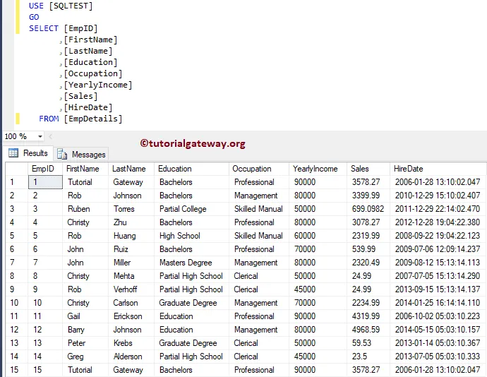
And the Destination table is Pre and Post SQL Employees. As you can see, it is an Empty table

Pre SQL and Post SQL in Informatica Example
Before we start configuring the Pre and Post SQL in Informatica, First connect to the Informatica repository service by providing the Admin Console Username and password that you specified while installing the Server.
Create Pre and Post SQL in Informatica Source Definition
Navigate to Source Analyzer and define your Sources. Here, we are using the EmpDetails table from the SQL Server database as our source definitions. I suggest you refer to Database Source to understand the creation of the source definition

Create Pre and Post SQL in Informatica Target Definition
Please navigate to Target Designer to define the Target. In this example, we are using the existing SQL table as our target definition. You can refer to Create Target table using Source Definition to understand the process of creating a target definition

Create Informatica Pre and Post SQL Mapping
To create a new mapping, Please navigate to the Mappings menu and select the Create.. option. It opens the Mapping Name window to write a unique name ( m_Pre_and_Post) and click the OK button.

Drag and drop the EmpDetails source definitions from Sources folder to the mapping designer. Once you drag the source, the Power Center designer will automatically create the Source Qualifier for you.

Double click on the Source Qualifier transformation, and go to properties Tab to configure the Informatica Pre and Post SQL
Pre: This property is used to run the Command against the Source before the Integration Service Starts. Click the arrow

Here we are writing an Insert Statement to insert new records into the Emp Details table before the integration service starts.

Post: Use this property to run the Command against the Source After the Integration Service Ends. Here, we are writing a Delete Statement to delete the record whose employee Id is equal to 9

You can also alter the remaining properties. But for now, we are clicking OK button to close the properties windows

Next, Drag and drop the target definition from Targets folder to the mapping designer. Next, join the source qualifier Transformation with the target definition using the Autolink.. option.
Before we close the Mapping, Let us Save, and Validate the mapping by going to Mapping Menu bar, and select the Validate option.

Create Informatica Pre and Post SQL Workflow
After we finish creating the Informatica Pre and Post SQL Mapping, we have to create the workflow for it. Power Center Workflow manager provides two approaches to create a workflow.
In this example, we will create the Workflow manually. First, navigate to Workflows Menu and select the Create option will open Create Workflow window. Please provide the unique name (wf_Pre_and_Post) and leave the default settings.

Once we created the workflow, our next step is to create a session task for our mapping.
Create Session for Pre and Post SQL
There are two types of sessions:
For this Informatica Pre and Post SQL example, we created a Non-reusable Session and named it as s_Pre_and_Post for the session.

Please link the Start Task, and the Session Task. Next, navigate to Workflows Menu and select the Validate option to validate the Workflow. From the below screenshot, you can observe that the workflow is a valid one.

Now, Let me start the Informatica Pre and Post SQL Workflow. To do so, navigate to the Workflows menu and select the Start Workflow option.
Let us open the Server Management Studio. As you can, it has 16 records: 15 from EmpDetails table, and 1 records from Insert Statement in Pre SQL

If you observe the original Table after the Integration process. There are 15 records
The Delete Statement in Post deleted the record with EmpID 9, and The Insert Statement in Pre SQL inserts new records.


 The PowerCenter Designer provides multiple ways to connect the source qualifier with the newly created Sorter Transformation in Informatica. For this example, we are right-clicking on the empty space and selecting the Autolink.. option from that context menu.


