Wi-Fi Signal Strength Reader and Haptic Feedback
When designing an embedded system with Internet connectivity using Wi-Fi, reading the Wi-Fi connections receiving signal allows the user to determine the available Internet connectivity and signal strength. Most devices show the signal strength to the consumer using a simple bar graph or something similar. In this project, however, we look into how to notify the signal strength level using a different kind of mechanism to the user: the haptic feedback.
Another technique is to send the Wi-Fi signal strength level over the Internet, which allows you to measure signal strength even in unreachable locations. In the previous chapter, you learned about Arduino Ethernet Web server. Here, similar implementations will be used.
In this chapter, you will do the following:
Learn about Arduino WiFi Shield basics and stacking with an Arduino UNO board
Learn how to read the receiving radio signal strength level using RSSI
Learn about vibration motors and haptic feedback
Learn about haptic motor controllers and the Adafruit haptic library
Write a simple web server to display the strength level of the received radio signal using a simple HTML web page
To complete this project, you may require some open source hardware, software, tools, and good soldering skills. Let's dive in one step at a time.
Arduino UNO board (http://store.arduino.cc/product/A000066)
Arduino WiFi Shield (http://store.arduino.cc/product/A000058)
Vibrating Mini Motor Disc (http://www.adafruit.com/product/1201)
Adafruit DRV2605L Haptic Motor Controller (http://www.adafruit.com/product/2305)
USB A to B cable
Wall adapter power supply 9V DC 650mA
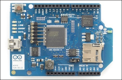
Arduino WiFi Shield allows you to connect your Arduino board to the Internet wirelessly. In the previous chapter, you learned how to connect the Arduino board to the Internet using an Ethernet shield with a wired connection. Unlike a wired connection, a wireless connection provides us with increased mobility within the Wi-Fi signal range, and the ability to connect to other Wi-Fi networks automatically, if the current network loses connection or has insufficient radio signal strength. Most of the mechanisms can be manipulated using the Arduino Wi-Fi library, a well-written piece of program sketch. The following image shows the top view of an Arduino WiFi Shield. Note that two rows of wire wrap headers are used to stack with the Arduino board.

Arduino WiFi Shield (top view) Image courtesy of Arduino (https://www.arduino.cc) and license at http://creativecommons.org/licenses/by-sa/3.0/
The following image shows the bottom view of an Arduino WiFi Shield:
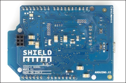
Arduino WiFi Shield (bottom view) Image courtesy of Arduino (https://www.arduino.cc) and license at http://creativecommons.org/licenses/by-sa/3.0/
Before using the Arduino WiFi Shield with this project, upgrade its firmware to version 1.1.0 or greater, as explained in the following official Arduino page at https://www.arduino.cc/en/Hacking/WiFiShieldFirmwareUpgrading.
The default factory-loaded firmware version 1.0.0 will not work properly with some of the Arduino sketches in this chapter.
Simply plug in to your Arduino WiFi Shield on top of the Arduino board using wire wrap headers so the pin layout of the Arduino board and the WiFi Shield will be exactly intact together.
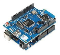
Arduino WiFi Shield is stacked with Arduino UNO
You can use the Arduino UNO REV3 board directly without any hacking for this project. However, you can still use an Arduino UNO board earlier than REV3 with a simple hack.
First, stack your Wi-Fi shield on the Arduino board, and then connect your Wi-Fi shield's IOREF pin to the 3.3V pin using a small piece of jumper wire.
The following image shows a wire connection from the 3.3V pin to the IOREF pin.
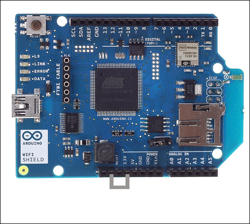
A jumper wire attached from 3.3V TO IOREF Image courtesy of Arduino (https://www.arduino.cc) and license at http://creativecommons.org/licenses/by-sa/3.0/
Note
Warning!
Later, when you stack the hacked WiFi shield on an Arduino REV3 board, remember to remove the jumper wire. Otherwise, you will be shorting 3.3V to 5V through the IOREF pin.
Your WiFi shield may have an SD card slot that communicates with your Arduino board via the digital pin 4. Arduino UNO communicates with the WiFi shield using digital pins 11, 12, and 13 over SPI bus. Also, the digital pin 10 is used as SS. Therefore, we will not use these pins with our project. However, you can use the digital pin 4 by using the following software hack.
pinMode(4, output);
digitalWrite(4, HIGH);
Before getting started with the WiFi library, you have to apply the following fixes to some of the files inside the Arduino WiFi library:
Navigate to the WiFi folder in the libraries folder
Open the wifi_drv.cpp file located in the utility folder under src.
Find the getCurrentRSSI() function and modify it as follows:
int32_t WiFiDrv::getCurrentRSSI()
{
startScanNetworks();
WAIT_FOR_SLAVE_SELECT();
// Send Command
SpiDrv::sendCmd(GET_CURR_RSSI_CMD, PARAM_NUMS_1);
uint8_t _dummy = DUMMY_DATA;
SpiDrv::sendParam(&_dummy, 1, LAST_PARA);
//Wait the reply elaboration
SpiDrv::waitForSlaveReady();
// Wait for reply
uint8_t _dataLen = 0;
int32_t rssi = 0;
SpiDrv::waitResponseCmd(GET_CURR_RSSI_CMD, PARAM_NUMS_1, (uint8_t*)&rssi, &_dataLen);
SpiDrv::spiSlaveDeselect();
return rssi;
}
Save and close the file.
To connect your Arduino WiFi shield to a Wi-Fi network, you should have the SSID of any available Wi-Fi network. SSID (Service Set Identifier) is the name of the Wi-Fi network that you want to connect to your Arduino WiFi shield. Some Wi-Fi networks require a password to connect it with and some are not, which means open networks.
The Arduino WiFi library provides an easy way to connect your WiFi shield to a Wi-Fi network with the WiFi.begin() function. This function can be called in different ways depending on the Wi-Fi network that you want to connect to.
WiFi.begin(); is only for initializing the Wi-Fi shield and called without any parameters.
WiFi.begin(ssid); connects your WiFi shield to an Open Network using only the SSID of the network, which is the name of the network. The following Arduino sketch will connect your Arduino WiFi shield to an open Wi-Fi network which is not password protected and anyone can connect. We assume that you have a Wi-Fi network configured as OPEN and named as MyHomeWiFi. Open a new Arduino IDE and copy the sketch named B04844_02_01.ino from the Chapter 2 sample code folder.
#include <SPI.h>
#include <WiFi.h>
char ssid[] = "MyHomeWiFi";
int status = WL_IDLE_STATUS;
void setup(){
Serial.begin(9600);
if (WiFi.status() == WL_NO_SHIELD){
Serial.println("No WiFi shield found"); while(true);
}
while ( status != WL_CONNECTED){
Serial.print("Attempting to connect to open SSID: ");
Serial.println(ssid);
status = WiFi.begin(ssid);
delay(10000);
}
Serial.print("You're connected to the network");
}
void loop (){
}
Modify the following line of the code according to your Wi-Fi network's name.
char ssid[] = "MyHomeWiFi";
Now verify and upload the sketch in to your Arduino board and then open the Arduino Serial Monitor. The Arduino Serial Monitor will display the status about the connection at the time it was connected similar to follows.
Attempting to connect to open SSID: MyHomeWiFi
You're connected to the network
WiFi.begin(ssid,pass); connects your WiFi shield to a WPA2 (Wi-Fi Protected Access II) personal encrypted secured Wi-Fi network using SSID and password. The shield will not connect to Wi-Fi networks that are encrypted using WPA2 Enterprise Encryption. We assume that you have a Wi-Fi network configured as WAP2 and named as MyHomeWiFi.
Open a new Arduino IDE and copy the sketch named B04844_02_02.ino from the Chapter 2 sample code folder.
#include <SPI.h>
#include <WiFi.h>
char ssid[] = "MyHomeWiFi";
char pass[] = "secretPassword";
int status = WL_IDLE_STATUS;
void setup(){
Serial.begin(9600);
if (WiFi.status() == WL_NO_SHIELD) {
Serial.println("WiFi shield not present");
while(true);
}
while ( status != WL_CONNECTED) {Serial.print("Attempting to connect to WPA SSID: ");
Serial.println(ssid);
status = WiFi.begin(ssid, pass);
delay(10000);
}
Serial.print("You're connected to the network");
}
void loop(){
}
Modify the following line of the code according to your Wi-Fi network's name.
char ssid[] = "MyHomeWiFi";
Now verify and upload the sketch in to your Arduino board and then open the Arduino Serial Monitor. The Arduino Serial Monitor will display the status about the connection at the time it was connected similar to follows.
Attempting to connect to WPA SSID: MyHomeWiFi
You're connected to the network
WiFi.begin(ssid, keyIndex, key); is only for use with WEP encrypted Wi-Fi networks. WEP networks can have up to four passwords in hexadecimals that are known as keys. Each key is assigned a Key Index value. Configure your Wi-Fi network as a WEP encryption and upload the following sketch into your Arduino board. But remember the WEP is not secure at all and don't use it with your Wi-Fi networks. Instead of that use WPA2 encryption which is highly recommended.
We assume that you have a Wi-Fi network configured as WPE and named as MyHomeWiFi. Change the configuration back to the WPA2 as quickly as possible after testing the following code snippet. Open a new Arduino IDE and copy the sketch named B04844_02_03.inofrom the Chapter 2 sample code folder.
#include <SPI.h>
#include <WiFi.h>
char ssid[] = "MyHomeWiFi";
char key[] = "D0D0DEADF00DABBADEAFBEADED";
int keyIndex = 0;
int status = WL_IDLE_STATUS;
void setup(){
Serial.begin(9600);
if (WiFi.status() == WL_NO_SHIELD) {
Serial.println("WiFi shield not present"); while(true);
}
while ( status != WL_CONNECTED) { Serial.print("Attempting to connect to WEP network, SSID: ");
Serial.println(ssid);
status = WiFi.begin(ssid, keyIndex, key);
delay(10000);
}
Serial.print("You're connected to the network");
}
void loop(){
}
Modify the following line of the code according to your Wi-Fi network's name:
char ssid[] = "MyHomeWiFi";
Now verify and upload the sketch in to your Arduino board and then open the Arduino Serial Monitor. The Arduino Serial Monitor will display the status about the connection at the time it was connected similar to follows.
Attempting to connect to WEP network, SSID: MyHomeWiFi
You're connected to the network
The Arduino WiFi library provides us with a simple way to get the Wi-Fi signal strength in decibels ranging from 0 to -100 (minus 100). You can use the WiFi.RSSI() function to get the radio signal strength of the currently connected network or any specified network. You can read more about Received Signal Strength Indication (RSSI) at https://en.wikipedia.org/wiki/Received_signal_strength_indication.
The WiFi.RSSI() function can be called with following parameters:
WiFi.RSSI();:This will return the signal strength of the currently connected Wi-Fi network.
WiFi.RSSI(WiFi Access Point);: This will return the signal strength of a specified Wi-Fi network. Wi-Fi Access Point is the name of the Wi-Fi network. For example, MyHomeWiFi.
Now we will write an Arduino sketch to get the RSSI value of the currently connected Wi-Fi network.
Open a new Arduino IDE and copy the sketch named B04844_02_04.ino from the Chapter 2 sample code folder.
#include <SPI.h>
#include <WiFi.h>
char ssid[] = "MyHomeWiFi";
char pass[] = "secretPassword";
void setup()
{
WiFi.begin(ssid, pass);
if (WiFi.status() != WL_CONNECTED) { Serial.println("Couldn't get a wifi connection");
while(true);
} else
{
long rssi = WiFi.RSSI();
Serial.print("RSSI: ");
Serial.print(rssi);
Serial.println(" dBm");
}
}
void loop (){
}
Modify the following line of the code according to your Wi-Fi network's name.
char ssid[] = "MyHomeWiFi";
Now verify and upload the sketch in to your Arduino board and then open the Arduino Serial Monitor.
The Arduino Serial Monitor will display the received signal in dBm (decibel-milliwatts) for the currently connected Wi-Fi network similar to the following:
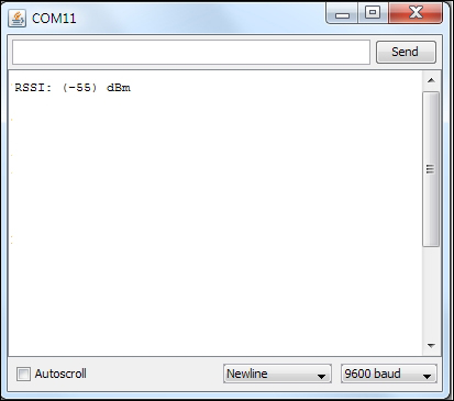
However, note that this will only provide the signal strength at the moment the WiFi shield was connected to the Wi-Fi network.
In the next Arduino sketch, we are going to look at how to display the Wi-Fi signal strength and update it periodically.
Open a new Arduino IDE and copy the sketch named B04844_02_05.ino from the Chapter 2 sample code folder.
#include <SPI.h>
#include <WiFi.h>
char ssid[] = "MyHomeWiFi";
char pass[] = "secretPassword";
void setup()
{
WiFi.begin(ssid, pass);
}
void loop (){
if (WiFi.status() != WL_CONNECTED) { Serial.println("Couldn't get a wifi connection");
while(true);
}
else
{
long rssi = WiFi.RSSI();
Serial.print("RSSI: ");
Serial.print(rssi);
Serial.println(" dBm");
}
delay(10000);//waits 10 seconds and update
}
Modify the following line of the code according to your WiFi network's name:
char ssid[] = "MyHomeWiFi";
Now verify and upload the sketch in to your Arduino board and then open the Arduino Serial Monitor.
The Arduino Serial Monitor will display the received signal in dBm (decibel-milliwatts) for the currently connected Wi-Fi network similar to the following:

In the next section of this chapter, we will look at how to integrate a vibrator to the Arduino WiFi shield and output advanced vibration patterns according to the current RSSI value.
Haptic feedback is the way to convey information to users using advanced vibration patterns and waveforms. Earlier consumer electronic devices communicated with their users using audible and visual alerts, but now things have been replaced with vibrating alerts through haptic feedback.
In a haptic feedback system, the vibrating component can be a vibration motor or a linear resonant actuator. The motor is driven by a special hardware called the haptic controller or haptic driver. Throughout this chapter we use the term vibrator for the vibration motor.
Adafruit DRV2605 haptic controller is an especially designed motor controller for controlling haptic motors. With a haptic controller, you can make various effects using a haptic motor such as:
Ramping the vibration level up and down
Click, double-click, and triple-click effects
Pulsing effects
Different buzzer levels
Vibration following a musical/audio input
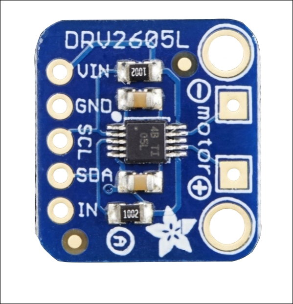
The DRV2605 breakout board (top view) Image courtesy of Adafruit Industries (https://www.adafruit.com)
Vibrators come with various shapes and driving mechanisms. Some of them support haptic feedback while some do not. Before purchasing a vibrator, check the product details carefully to determine whether it supports haptic feedback. For this project, we will be using a simple vibrating mini motor disc, which is a small disc-shaped motor. It has negative and positive leads to connect with the microcontroller board.
The following image shows a vibrator with positive and negative wires soldered:

Fritzing representation of a vibrator
Use the following steps to connect the DRV2605 haptic controller to Arduino WiFi Shield:
Solder headers to the DRV2605 breakout board, connect it to a breadboard and then user jumper wires for the connection to the Arduino.
Connect the VIN pin of the DRV2605 breakout board to the 5V pin of the Arduino WiFi Shield.
Connect the GND pin of the DRV2605 breakout to the GND pin of the Arduino WiFi Shield.
Connect the SCL pin of the DRV2605 breakout board to the Analog 5 (A5) pin of the Arduino WiFi Shield.
Finally, connect the SDA pin of the DRV2605 breakout board to the Analog 4 (A4) pin of the Arduino WiFi Shield.
The following image shows the connection between DRV2605 breakout board and Arduino WiFi shield:
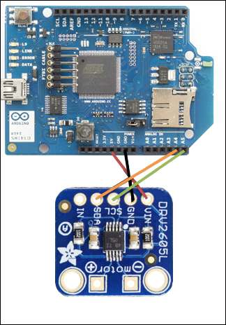
Image courtesy of Arduino (https://www.arduino.cc) and license at http://creativecommons.org/licenses/by-sa/3.0/, and Adafruit Industries (https://www.adafruit.com)
On the DRV2605 breakout board, you can see two square shaped soldering pads marked as + and - along with the motor text label. This is the place where we are going to solder the vibrator. Generally vibrators have two presoldered wires, red and black.
Solder the red wire of the vibrator to the + soldering pad of the breakout board
Solder the blue wire of the vibrator to the – soldering pad of the breakout board
The following image shows the final connection between DRV2605 breakout board, Arduino WiFi shield and the vibrator:
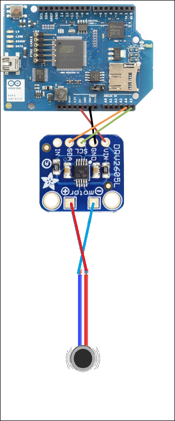
Image courtesy of Arduino (https://www.arduino.cc) and license at http://creativecommons.org/licenses/by-sa/3.0/, and Adafruit Industries (https://www.adafruit.com)
You can download the latest version of the Adafruit DRV2605 library from the GitHub repository by navigating to the following URL: https://github.com/adafruit/Adafruit_DRV2605_Library.
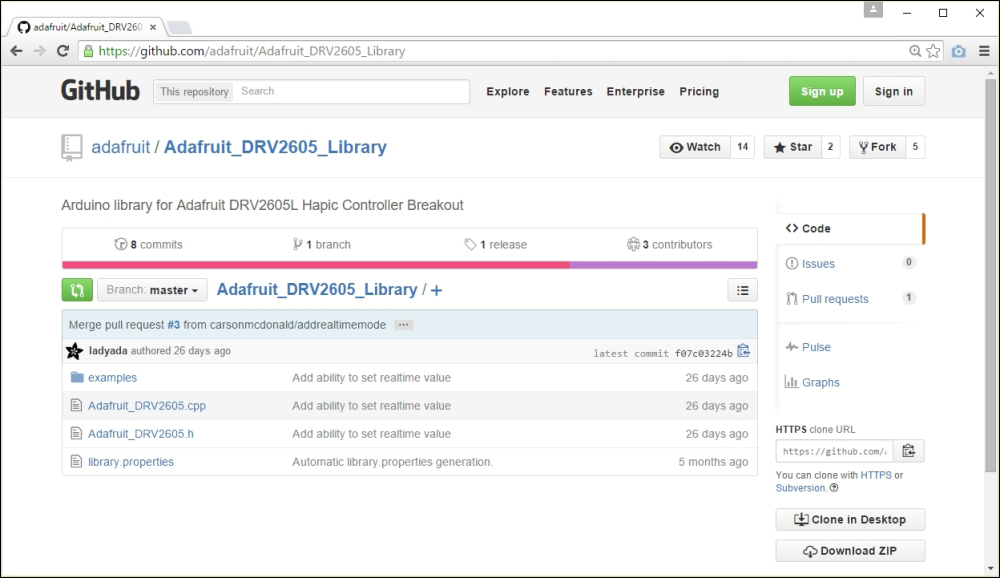
The Adafruit DRV2605 library at GitHub
After navigating to the earlier URL, follow these steps to download Adafruit DRV2605 library:
Click on the Download Zip button.
After downloading the ZIP file, extract it to your local drive and rename it as Adafruit_DRV2605. Then copy or move the folder inside the Arduino libraries folder. Finally, restart the Arduino IDE.
Open the sample sketch included with the library by clicking on File | Examples | Adafruit_DRV2605 | basic and upload it to your Arduino board. The sketch will play 116 vibration effects defined in the DRV2605 library from effect number 1 to 116 in order.
You can download the datasheet for DRV2605 Haptic Driver from http://www.ti.com/lit/ds/symlink/drv2605.pdf and refer to pages 55-56 for the full set of 123 vibration effects. The DRV2605 haptic driver is manufacturing by Texas Instruments.
Now, we will learn how to make different vibration effects depending on the Received Signal Strength Indication (RSSI). Typically, RSSI value rages from 0 to -100. The higher the value, the stronger the signal reception where 0 is the highest value. Therefore, we can logically check the RSSI value return by the WiFi.RSSI() function and play vibration effects accordingly.
In the following example, we will play the first 10 vibration effects according to the RSSI value output by the Arduino WiFi shield. See the following chart for the RSSI value range for each vibration effect:
|
Effect Number |
RSSI |
|
|
1 |
0 |
-10 |
|
2 |
-11 |
-20 |
|
3 |
-21 |
-30 |
|
4 |
-31 |
-40 |
|
5 |
-41 |
-50 |
|
6 |
-51 |
-60 |
|
7 |
-61 |
-70 |
|
8 |
-71 |
-80 |
|
9 |
-81 |
-90 |
|
10 |
-91 |
-100 |
Following steps shows how to generate different vibration effects according to the RSSI strength of the currently connected Wi-Fi network.
Open a new Arduino IDE and copy the sketch named B04844_02_06.ino from the Chapter 2 sample code folder.
Modify the following line of the code according to your Wi-Fi network's name:
char ssid[] = "MyHomeWiFi";
Following line maps RSSI output to the value range from 1 to 10 using the map() function:
int range = map(rssi, -100, 0, 1, 10);
Set the vibration effect using the setWaveform(slot, effect) function by passing the parameters such as slot number and effect number. Slot number starts from 0 and effect number can be found in the waveform library effect list.
Finally call the go() function to play the effect.
The following code block shows first how to set and play the waveform double click – 100%:
drv.setWaveform(0, 10); // play double click - 100%drv.setWaveform(1, 0); // end waveform
drv.go(); // play the effect!
Verify and upload the sketch in to your Arduino board. Now touch the vibrator and feel the different vibration effects according to the variations of WiFi signal strength of the currently connected network. You can test this by moving your Wi-Fi router away from the Arduino WiFi shield.
Tip
Downloading the example code
You can download the example code files from your account at http://www.packtpub.com for all the Packt Publishing books you have purchased. If you purchased this book elsewhere, you can visit http://www.packtpub.com/support and register to have the files e-mailed directly to you.
The Arduino WiFi Shield can also be configured and programmed as a web server to serve client requests similar to the Arduino Ethernet shield. In the next step, we will be making a simple web server to send Wi-Fi signal strength over the Internet to a client. This requires that the WiFi shield has 1.1.0 firmware to work. The default factory loaded version 1.0.0 will not work. (See the Firmware upgrading section.)
To read the signal strength over Wi-Fi:
Open a new Arduino IDE and copy the sketch named B04844_02_07.ino from the Chapter 2 sample code folder.
Verify and upload the Arduino sketch in to the Arduino board. Type the IP address of your WiFi shield in your web browser and hit the Enter key. The web page will load and display the current RSSI of the Wi-Fi network and refresh every 20 seconds. If you don't know the IP address of your Arduino WiFi shield assigned by the DHCP, open the Arduino Serial Monitor and you can find it from there.
In this chapter, we learnt how to read Wi-Fi signal strength with a WiFi shield and make haptic feedback using a vibration motor according to the Wi-Fi signal strength. Further, we learned to use haptic feedback libraries to make feedback patterns.