Parking is one of the biggest problems in modern cities. A smart parking system is a solution to address vehicle parking in cities using the internet. This chapter will explore what a smart parking system is and how to build one using Arduino and Raspberry Pi boards.
In this chapter, we learn the following topics:
Introducing smart parking systems
Sensor devices for a smart parking system
Vehicle entry/exit detection
Vehicle plate number detection
Vacant parking space detection
Building a smart parking system
Let's get started!
Parking has become one of the biggest problems in modern cities. When the vehicle growth rate is faster than street development rate, there will be issues with how these vehicles will be parked. A smart parking system becomes an alternative solution to addressing parking problems.
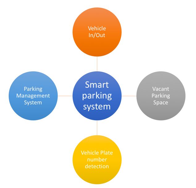
In general, a smart parking system will address problems shown in the following figure:

Vehicle In/Out stands for detecting when a vehicle comes in and goes out. It will affect the number of vacant parking spaces and parking duration.
Vehicle plate number detection aims at minimizing human errors in entering vehicle plate numbers into a system.
Vacant parking space aims at optimizing parking space by knowing the number of vacant parking spaces.
Parking management system is the main system to manage all activities in a parking system. It also provides information about vacant parking spaces to users through a website and mobile application.
In this chapter, we will explore several problems in parking systems and address them using automation.
To build a smart parking system, we should know about some sensors related to a smart parking system. In this section, we will review the main sensors that are used in one.
Let's explore!
The HC-SR04 is a cheap ultrasonic sensor. It is used to measure the range between itself and an object. Each HC-SR04 module includes an ultrasonic transmitter, a receiver, and a control circuit. You can see that the HC-SR04 has four pins: GND, VCC, Triger, and Echo. You can buy HC-SR04 from SparkFun, at https://www.sparkfun.com/products/13959, as shown in the next image. You can also find this sensor at SeeedStudio: https://www.seeedstudio.com/Ultra-Sonic-range-measurement-module-p-626.html. To save money, you can buy the HC-SR04 sensor from Aliexpress.
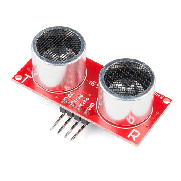
The HR-SR04 has four pins. There are VCC, GND, Echo, and Trigger. We can use it with Arduino, Raspberry Pi, or other IoT boards.
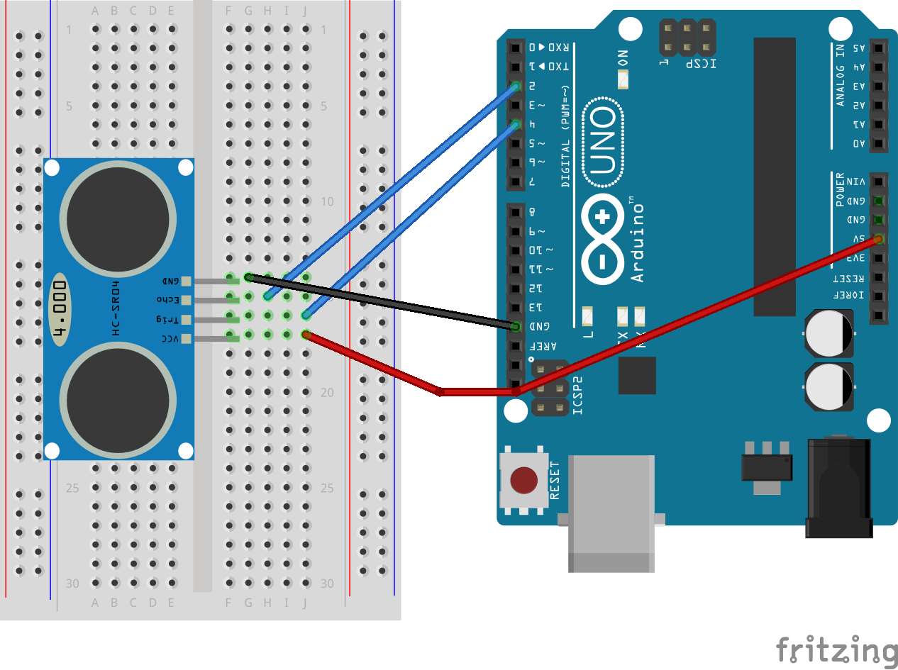
For demonstration, we can develop a simple application to access the HC-SR04 on an Arduino board. You can do the following wiring:
HC-SR04 VCC is connected to Arduino 5V
HC-SR04 GND is connected to Arduino GND
HC-SR04 Echo is connected to Arduino Digital 2
HC-SR04 Trigger is connected to Arduino Digital 4
You can see the hardware wiring in the following figure:
To work with the HC-SR04 module, we can use the NewPing library on our Sketch program. You can download it from http://playground.arduino.cc/Code/NewPing and then deploy it into the Arduino libraries folder. After it is deployed, you can start writing your Sketch program.
Now you can open your Arduino software. Then write the following complete code for our Sketch program:
#include <NewPing.h>
#define TRIGGER_PIN 2
#define ECHO_PIN 4
#define MAX_DISTANCE 600
NewPing sonar(TRIGGER_PIN, ECHO_PIN, MAX_DISTANCE);
long duration, distance;
void setup() {
pinMode(13, OUTPUT);
pinMode(TRIGGER_PIN, OUTPUT);
pinMode(ECHO_PIN, INPUT);
Serial.begin(9600);
}
void loop() {
digitalWrite(TRIGGER_PIN, LOW);
delayMicroseconds(2);
digitalWrite(TRIGGER_PIN, HIGH);
delayMicroseconds(10);
digitalWrite(TRIGGER_PIN, LOW);
duration = pulseIn(ECHO_PIN, HIGH);
//Calculate the distance (in cm) based on the speed of sound.
distance = duration/58.2;
Serial.print("Distance=");
Serial.println(distance);
delay(200);
}
Save this sketch as ArduinoHCSR04.
This program will initialize a serial port at baudrate 9600 and activate digital pins for the HC-SR04 in the setup() function. In the loop() function, we read the value of the distance from the sensor and then display it on the serial port.
You can compile and upload this sketch to your Arduino board. Then you can open the Serial Monitor tool from the Arduino IDE menu. Make sure you set your baudrate to 9600.
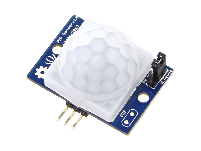
A Passive Infrared Detection (PIR) motion sensor is used to object movement. We can use this sensor for detecting vehicle presence. PIR sensors can be found on SeeedStudio at https://www.seeedstudio.com/PIR-Motion-Sensor-Large-Lens-version-p-1976.html, Adafruit at https://www.adafruit.com/product/189, and SparkFun at https://www.sparkfun.com/products/13285. PIR motion sensors usually have three pins: VCC, GND, and OUT.
The OUT pin is digital output on which if we get value 1, it means motion is detected. You can see the PIR sensor from SeeedStudio here:
There's another PIR motion sensor from SparkFun, the SparkFun OpenPIR: https://www.sparkfun.com/products/13968. This sensor provides analog output so we can adjust the motion detection value. You can see the SparkFun OpenPIR here:
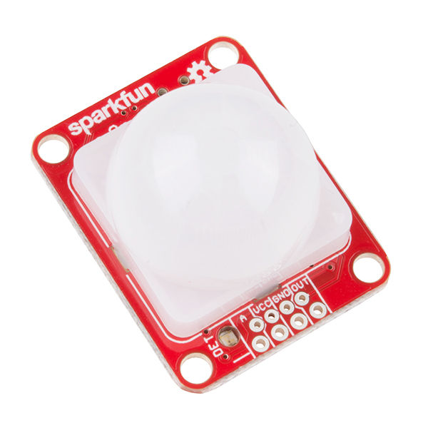
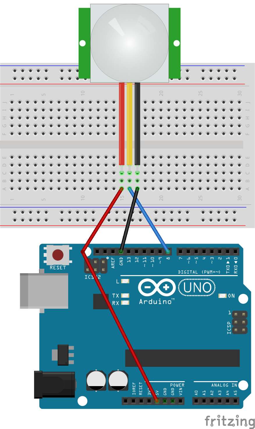
For testing, we develop an Arduino application to access the PIR motion sensor. We will detect object motion using the PIR motion sensor. You can perform the following hardware wiring:
PIR Sensor VCC is connected to Arduino 5V
PIR Sensor GND is connected to Arduino GND
PIR Sensor OUT is connected to Arduino Digital 8
You can see the complete wiring here:
Now we can write a sketch program using Arduino software. To read object motion detection in digital form, we can use digitalRead(). If the program detects object motion, we turn on the LED. Otherwise, we turn it off.
Here is the complete sketch:
#define PIR_LED 13 // LED
#define PIR_DOUT 8 // PIR digital output on D8
int val = 0;
int state = LOW;
void setup()
{
pinMode(PIR_LED, INPUT);
pinMode(PIR_DOUT, INPUT);
Serial.begin(9600);
}
void loop()
{
val = digitalRead(PIR_DOUT);
if(val==HIGH)
{
digitalWrite(PIR_LED, HIGH);
if(state==LOW) {
Serial.println("Motion detected!");
state = HIGH;
}
}else{
digitalWrite(PIR_LED, LOW);
if (state == HIGH){
Serial.println("Motion ended!");
state = LOW;
}
}
}
Save this sketch as ArduinoPIR.
You can compile and upload the program to your Arduino board. To see the program output, you can open the Serial Monitor tool from Arduino. Now you test motion detection using your hand and see the program output in the Serial Monitor tool.
Next, we will use the SparkFun OpenPIR or other PIR motion sensor. Based on its datasheet, the SparkFun OpenPIR has similar pins similar to PIR motion sensors. However, the SparkFun OpenPIR sensor has an additional pin, the AOUT analog output.
This pin provides analog output as a voltage value from the object's motion level. From this case, we set the object motion-detection level based on the analog output.
For testing, we'll develop a sketch program using the SparkFun OpenPIR and Arduino. You can build the following hardware wiring:
OpenPIR Sensor VCC is connected to Arduino 5V
OpenPIR Sensor GND is connected to Arduino GND
OpenPIR Sensor AOUT is connected to Arduino Analog A0
OpenPIR Sensor OUT is connected to Arduino Digital 2
Now we'll modify the code sample from SparkFun. To read analog input, we can use analogRead() in our sketch program. Write this sketch for our demo:
#define PIR_AOUT A0 // PIR analog output on A0
#define PIR_DOUT 2 // PIR digital output on D2
#define LED_PIN 13 // LED to illuminate on motion
void setup()
{
Serial.begin(9600);
// Analog and digital pins should both be set as inputs:
pinMode(PIR_AOUT, INPUT);
pinMode(PIR_DOUT, INPUT);
// Configure the motion indicator LED pin as an output
pinMode(LED_PIN, OUTPUT);
digitalWrite(LED_PIN, LOW);
}
void loop()
{
int motionStatus = digitalRead(PIR_DOUT);
if (motionStatus == HIGH)
digitalWrite(LED_PIN, HIGH); // motion is detected
else
digitalWrite(LED_PIN, LOW);
// Convert 10-bit analog value to a voltage
unsigned int analogPIR = analogRead(PIR_AOUT);
float voltage = (float) analogPIR / 1024.0 * 5.0;
Serial.print("Val: ");
Serial.println(voltage);
}
Save it as ArduinoOpenPIR.
You can compile and upload the sketch to your Arduino board. Open the Serial Monitor tool to see the program output. Now you can move your hand and see the program output in the Serial Monitor tool.
The Hall Effect sensor works on the principle of the Hall Effect of magnetic fields. The sensor will generate a voltage that indicates whether the sensor is in the proximity of a magnet or not. This sensor is useful to detect vehicular presence, especially vehicles coming in and going out of the parking area.
There are ICs and modules that implement the Hall Effect. For instance, you can use a transistor, US1881. You can read about and buy this sensor from SparkFun (https://www.sparkfun.com/products/9312). This transistor may also be available in your local electronic store:

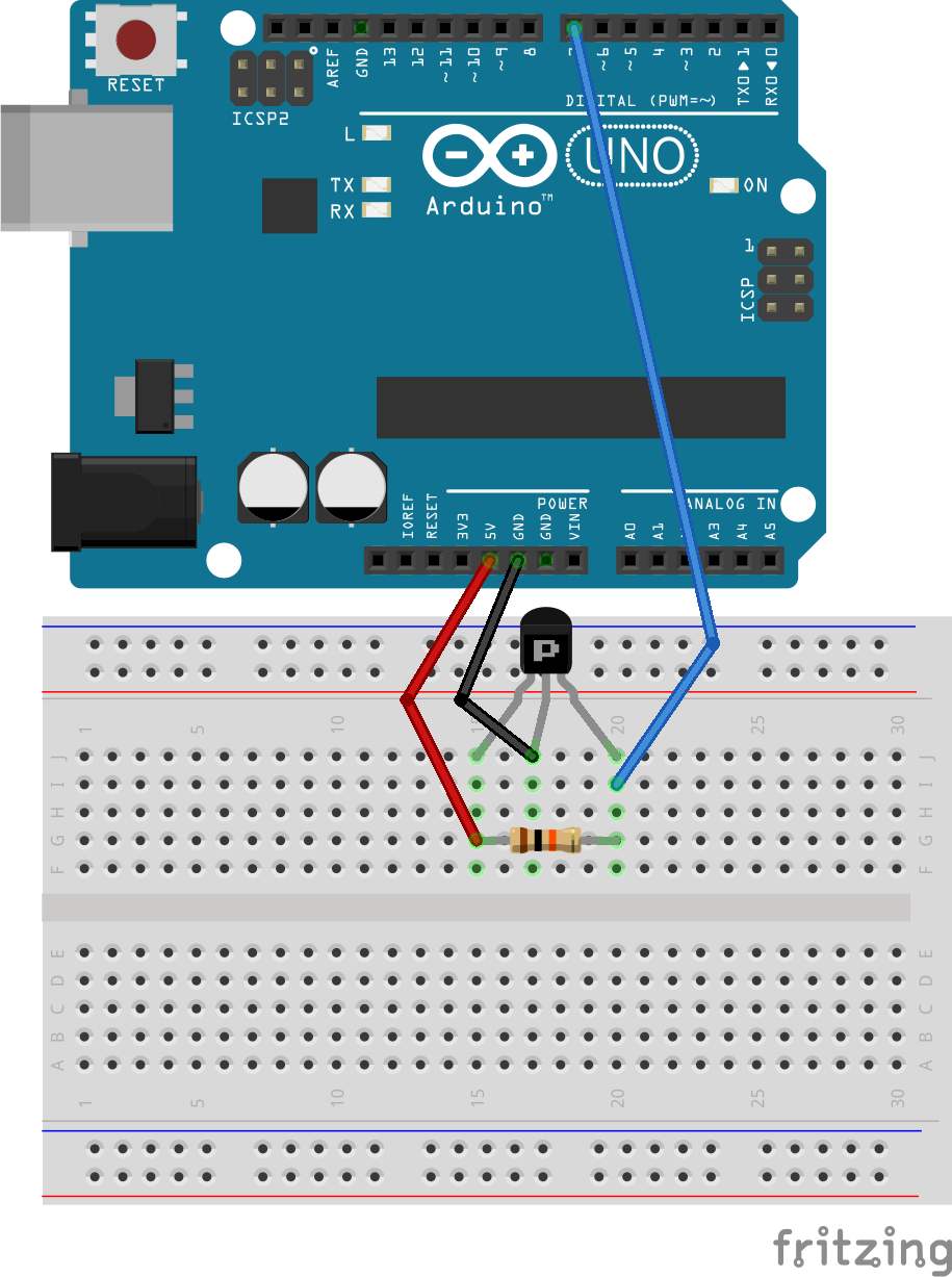
Now we can try to develop sketch program to read a magnetic value from a Hall Effect sensor. We will use the US1881. You can also use any Hall Effect chip according to your use case. Firstly, we'll make our hardware wiring as follows:
US1881 VCC is connected to Arduino 5V
US1881 GND is connected to Arduino GND
US1881 OUT is connected to Arduino Digital 7
A resistor of 10K ohms is connected between US1881 VCC and US1881 OUT
You can see the complete hardware wiring here:
We can now start writing our sketch program. We'll use digitalRead() to indicate a magnet's presence. If the digital value is LOW, we'll detect the magnet's presence. Write this program:
int Led = 13 ;
int SENSOR = 7 ;
int val;
void setup ()
{
Serial.begin(9600);
pinMode(Led, OUTPUT) ;
pinMode(SENSOR, INPUT) ;
}
void loop ()
{
val = digitalRead(SENSOR);
if (val == LOW)
{
digitalWrite (Led, HIGH);
Serial.println("Detected");
}
else
{
digitalWrite (Led, LOW);
}
delay(1000);
}
Save this sketch as ArduinoHallEffect.
You can compile and upload the program to your Arduino board. To see the program output, you can open the Serial Monitor tool from Arduino. For testing, you can use a magnet and put it next to the sensor. You should see "Detected" on the Serial Monitor tool.
A camera is a new approach for parking sensors. Using image processing and machine learning, we can detect vehicles coming in to/going out of a parking area. A camera is also useful for a vehicle's plate number detection.
If we implement a camera with a Raspberry Pi, we have many options. The Raspberry Pi Foundation makes the official camera for Raspberry Pi. Currently, the recommended camera is the camera module version 2. You can read about and buy it from https://www.raspberrypi.org/products/camera-module-v2/. You can see the the Pi Camera module V2 here:
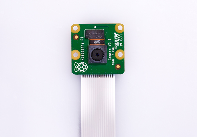
If you are working in low light conditions, the Pi Camera module V2 is not good at taking photos and recording. The Raspberry Pi Foundation provides the Pi Camera Noire V2. This camera can work in low light. You can find this product at https://www.raspberrypi.org/products/pi-noir-camera-v2/. You can see the Pi Camera Noire V2 here:
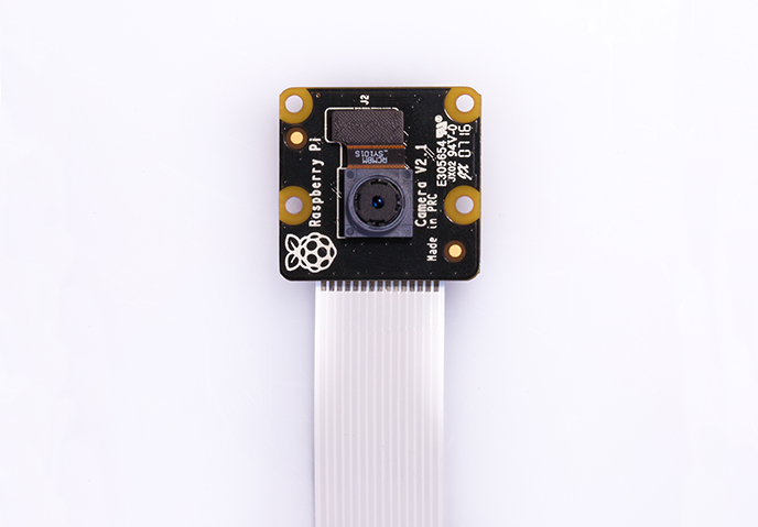
This camera module is connected to the Raspberry Pi through the CSI interface. To use this camera, you should activate it in your OS. For instance, if we use the Raspbian OS, we can activate the camera from the command line. You can type this command:
$ sudo apt-get update
$ sudo raspi-config
After it is executed, you should get the following menu:
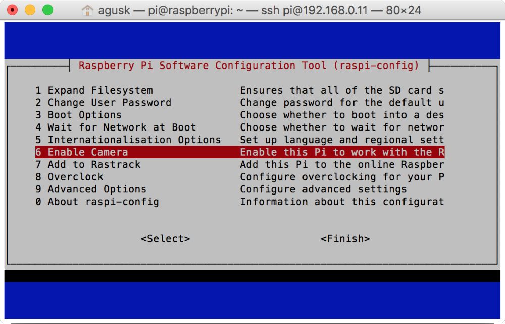
Select 6 Enable Camera to activate the camera on the Raspberry Pi. You'll get a confirmation to enable the camera module, as shown here:
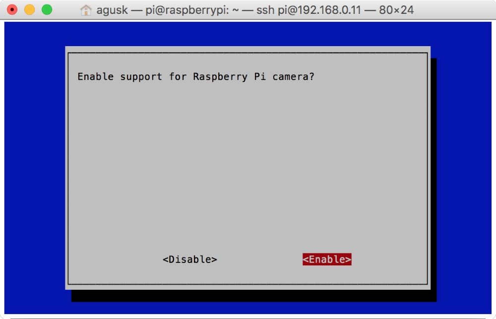
After this, Raspbian will reboot.
Now you can attach the Pi camera on the CSI interface. You can see my Pi camera here:
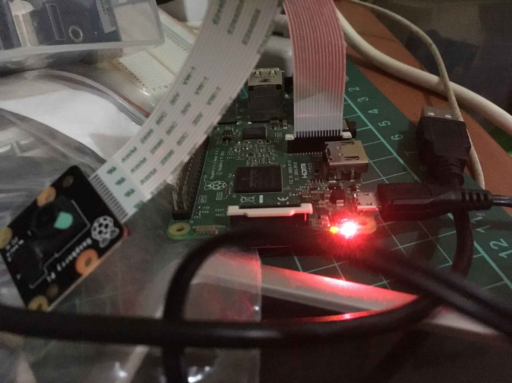
After it's attached, it's recommended you reboot your Raspberry Pi. If rebooting is done, you can verify whether the camera on the CSI interface is detected or not. You can use vcgencmd to check it. Type this command:
$ vcgencmd get_camera
You should see your camera detected in the terminal. For instance, you can see my response from the Pi camera here:
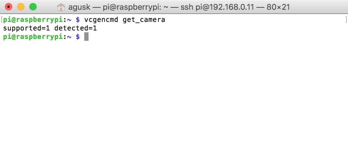
For testing, we'll develop a Python application to take a photo and save it to local storage. We'll use the PiCamera object to access the camera.
Use this script:
from picamera import PiCamera
from time import sleep
camera = PiCamera()
camera.start_preview()
sleep(5)
camera.capture('/home/pi/Documents/image.jpg')
camera.stop_preview()
print("capture is done")
Save it into a file called picamera_still.py. Now you can run this file on your Terminal by typing this command:
$ python picamera_still.py
If you succeed, you should see an image file, image.jpg:

A parking lot usually has an in-gate and out-gate. When a vehicle comes in, a driver presses a button to a get parking ticket. Then, the gate opens. Some parking places use a card as driver identity. After it is tapped, the gate will open.
Here's a real parking gate:
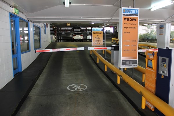
Source: http://queenland.co.id/secure-parking/
To build a parking in-gate, we can design one as shown in the following figure. We put sensor devices on the left, right, and a front of a vehicle. You can use sensor devices that we have learned about.
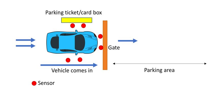
For instance, we can use an ultrasonic sensor. We'll put some sensor devices on the right, left, and front of the vehicle. The sensor device position in the gate is shown in the following figure. All sensors acquire and obtain distance values, dx. Then, we set a threshold value from a collection of distance values to indicate whether a vehicle is present.
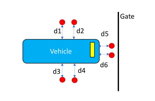
The out-gate has a similar design like the parking in-gate. You should modify the gate and sensor position based on the gate's position and size. Each gate will be identified as an in-gate or out-gate.
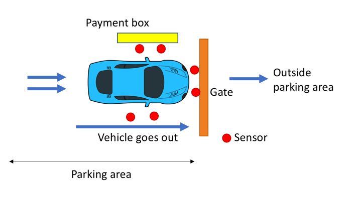
A gate will open if the driver has taken a parking ticket or taps a parking card. This scenario can be made automatic. For instance, we put a camera in front of the vehicle. This camera will detect the vehicle plate number. After detecting the plate number of the vehicle, the parking gate will open.
We will learn how to detect and identify plate numbers on vehicles using a camera in the next section.
A smart parking system ensures all activities take place automatically. Rather than reading a vehicle plate number manually, we can make it read a vehicle plate number using a program through a camera. We can use the OpenALPR library for reading vehicle plate numbers.
OpenALPR is an open source automatic license plate recognition library written in C++ with bindings in C#, Java, Node.js, Go, and Python. You can visit the official website at https://github.com/openalpr/openalpr.
We will install OpenALPR and test it with vehicle plate numbers in the next section.
In this section, we will deploy OpenALPR on the Raspberry Pi. Since OpenALPR needs more space on disk, make sure your Raspberry has space. You may need to expand your storage size.
Before we install OpenALPR, we need to install some prerequisite libraries to ensure correct installation. Make sure your Raspberry Pi is connected to the internet. You can type these commands to install all prerequisite libraries:
$ sudo apt-get update
$ sudo apt-get upgrade
$ sudo apt-get install autoconf automake libtool
$ sudo apt-get install libleptonica-dev
$ sudo apt-get install libicu-dev libpango1.0-dev libcairo2-dev
$ sudo apt-get install cmake git libgtk2.0-dev pkg-config libavcodec-dev libavformat-dev libswscale-dev
$ sudo apt-get install python-dev python-numpy libjpeg-dev libpng-dev libtiff-dev libjasper-dev libdc1394-22-dev
$ sudo apt-get install libgphoto2-dev
$ sudo apt-get install virtualenvwrapper
$ sudo apt-get install liblog4cplus-dev
$ sudo apt-get install libcurl4-openssl-dev
$ sudo apt-get install autoconf-archive
Once this is done, we should install the required libraries, such as Leptonica, Tesseract, and OpenCV. We will install them in the next few steps.
In this step, we'll install the Leptonica library. It's a library to perform image processing and analysis. You can get more information about the Leptonica library from the official website at http://www.leptonica.org. To install the library on the Raspberry Pi, we'll download the source code from Leptonica and then compile it. Right now, we'll install the latest version of the Leptonica library, version 1.74.1. You can use these commands:
$ wget http://www.leptonica.org/source/leptonica-1.74.1.tar.gz
$ gunzip leptonica-1.74.1.tar.gz
$ tar -xvf leptonica-1.74.1.tar
$ cd leptonica-1.74.1/
$ ./configure
$ make
$ sudo make install
This installation takes more time, so ensure all prerequisite libraries have been installed properly.
After installing the Leptonica library, we should install the Tesseract library. This library is useful for processing OCR images. We'll install the Tesseract library from its source code on https://github.com/tesseract-ocr/tesseract. The following is a list of commands to install the Tesseract library from source:
$ git clone https://github.com/tesseract-ocr/tesseract
$ cd tesseract/
$ ./autogen.sh
$ ./configure
$ make -j2
$ sudo make install
This installation process takes time. After it is done, you also can install data training files for the Tesseract library using these commands:
$ make training
$ sudo make training-install
The last required library to install OpenALPR is OpenCV. It's a famous library for computer vision. In this scenario, we will install OpenCV from source. It takes up more space on disk, so your Raspberry Pi disk should have enough free space. For demonstration, we'll install the latest OpenCV library. Version 3.2.0 is available on https://github.com/opencv/opencv. You can find the contribution modules on https://github.com/opencv/opencv_contrib. We also need to install modules with the same version as our OpenCV version.
First, we'll download and extract the OpenCV library and its modules. Type these commands:
$ wget https://github.com/opencv/opencv/archive/3.2.0.zip
$ mv 3.2.0.zip opencv.zip
$ unzip opencv.zip
$ wget https://github.com/opencv/opencv_contrib/archive/3.2.0.zip
$ mv 3.2.0.zip opencv_contrib.zip
$ unzip opencv_contrib.zip
Now we'll build and install OpenCV from source. Navigate your Terminal to the folder where the OpenCV library was extracted. Let's suppose our OpenCV contribution module has been installed at ~/Downloads/opencv_contrib-3.2.0/modules. You can change this based on where your OpenCV contribution module folder was extracted.
$ cd opencv-3.2.0/
$ mkdir build
$ cd build/
$ cmake -D CMAKE_BUILD_TYPE=RELEASE \
-D CMAKE_INSTALL_PREFIX=/usr/local \
-D INSTALL_PYTHON_EXAMPLES=ON \
-D OPENCV_EXTRA_MODULES_PATH=~/Downloads/opencv_contrib-3.2.0/modules \
-D BUILD_EXAMPLES=ON ..
$ make
$ sudo make install
$ sudo ldconfig
This installation takes a while. It may take over two hours. Make sure there is no error in the installation process.
Finally, we'll install OpenALPR from source:
$ git clone https://github.com/openalpr/openalpr.git
$ cd openalpr/src/
$ cmake ./
$ make
$ sudo make install
$ sudo ldconfig
After all this is installed, you are ready for testing. If it's not, resolve your errors before moving to the testing section.
Now that we've installed OpenALPR on our Raspberry Pi, we can test it using several vehicle plate numbers.
For instance, we have a plate number image here. The number is 6RUX251. We can call alpr:
$ alpr lp.jpg
plate0: 10 results
- 6RUX251 confidence: 95.1969
- 6RUXZ51 confidence: 87.8443
- 6RUX2S1 confidence: 85.4606
- 6RUX25I confidence: 85.4057
- 6ROX251 confidence: 85.3351
- 6RDX251 confidence: 84.7451
- 6R0X251 confidence: 84.7044
- 6RQX251 confidence: 82.9933
- 6RUXZS1 confidence: 78.1079
- 6RUXZ5I confidence: 78.053
You can see the that the result is 6RUX251 with a confidence of 95.1969%.

Source image: http://i.imgur.com/pjukRD0.jpg
The second demo for testing is a plate number from Germany, in the file Germany_BMW.jpg. You can see it in the next image. The number is BXG505. Let's test it using aplr:
$ alpr Germany_BMW.jpg
plate0: 10 results
- 3XG5C confidence: 90.076
- XG5C confidence: 82.3237
- SXG5C confidence: 80.8762
- BXG5C confidence: 79.8428
- 3XG5E confidence: 78.3885
- 3XGSC confidence: 77.9704
- 3X65C confidence: 76.9785
- 3XG5G confidence: 72.5481
- 3XG5 confidence: 71.3987
- XG5E confidence: 70.6362
You can see that the result is not good. Now we'll specify that it is a plate number from Europe by passing the eu parameter.
$ alpr -c eu Germany_BMW.jpg
plate0: 10 results
- B0XG505 confidence: 91.6681
- BXG505 confidence: 90.5201
- BOXG505 confidence: 89.6625
- B0XG5O5 confidence: 84.2605
- B0XG5D5 confidence: 83.6188
- B0XG5Q5 confidence: 83.1674
- BXG5O5 confidence: 83.1125
- B0XG5G5 confidence: 82.485
- BXG5D5 confidence: 82.4708
- BOXG5O5 confidence: 82.2548
Now you can see that the plate number is detected correctly with a confidence 90.5201%.

Source image: http://vehicleplatex6.blogspot.co.id/2012/06/
In a smart parking system, information about vacant parking spaces is important. A simple method to identify how many vacant spaces are available is to count the difference between the parking lot capacity and the number of vehicles currently in the lot. This approach has a disadvantage because we don't know which parking areas are vacant. Suppose a parking lot has four levels. We should know whether a parking area level is full or not.
Suppose we have a parking area as shown in the next image. We can identify how many vacant parking spaces there are using image processing and pattern recognition.
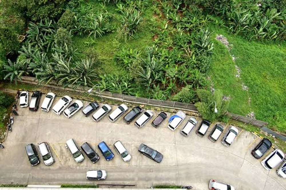
Source image: https://www.hotels.com/ho557827/jakarta-madrix-jakarta-indonesia/
A simple way to detect vacant parking spaces is to apply the background subtraction method. If you use the OpenCV library, you can learn this method with this tutorial: http://docs.opencv.org/3.2.0/d1/dc5/tutorial_background_subtraction.html.
The idea is that we capture all of the parking area without any vehicles. This will be used as a baseline background. Next, we can check whether a vehicle is present or not.
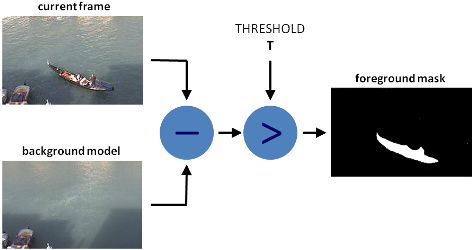
Source image: http://docs.opencv.org/3.2.0/d1/dc5/tutorial_background_subtraction.html
For another test, you can run a sample demo from https://github.com/eladj/detectParking. This application requires the OpenCV library. The application uses a template file to detect vehicle presence. For testing, you should run it on desktop mode. Open a terminal and run these commands:
$ git clone https://github.com/eladj/detectParkin
$ cd detectParking/cpp/
$ g++ -Wall -g -std=c++11 `pkg-config --cflags --libs opencv` ./*.cpp -o ./detect-parking
$ ./detect-parking ../datasets/parkinglot_1_480p.mp4 ../datasets/parkinglot_1.txt
You should see parking space detection as shown here:
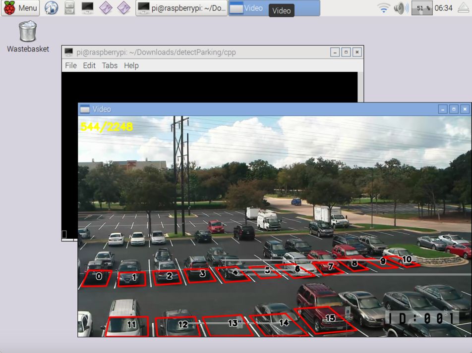
If you want to learn more about parking space detection and test your algorithm, you can use a dataset for testing from http://web.inf.ufpr.br/vri/news/parking-lot-database.
We have built sensors for detecting vehicle entry/exit and plate numbers. All those systems should be connected to a central system. This could be called a core system. To build a core system for parking, we could design and develop a parking management system. It's software which can use any platform, such as Java, .NET, Node.js, Python.
In general, a parking management system can be described as follows:
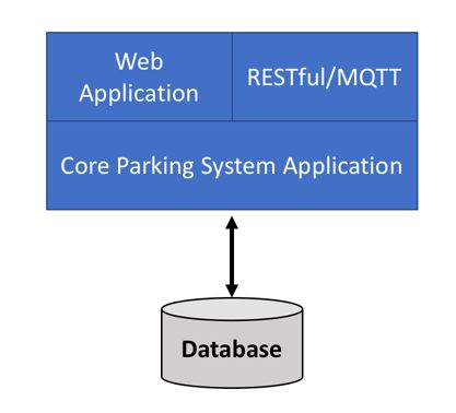
From this figure, we can explain each component as follows:
Core parking system application is the main application for the parking system. This application is responsible for processing and querying data for all vehicles and sensors.
Web application is a public application that serves parking information, such as capacity and current vacant parking space.
RESTful/MQTT is an application interface to serve JSON or MQTT for mobile and sensor applications.
Database is a database server that is used to store all data related to the parking application.
A database server is used to store all transactions in the parking system. We need to design a database schema based on our use case. Your database design should have plate number as transaction key. We'll record data for vehicle entry/exit. Lastly, you should design a parking pricing model. A simple pricing model is hourly--the vehicle will be charged at hourly intervals.
Now you can design your database. For demonstration, you can see my database design here:
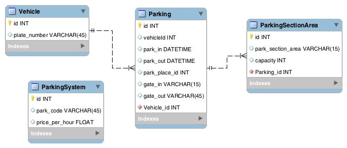
Here's an explanation of each table:
ParkingSystem is general information about the current parking lot. You can set an identity for your parking lot. This is useful if you want to deploy many parking spaces at different locations.
Vehicle is vehicle information. We should at least have plate numbers of vehicles.
ParkingSectionArea is information about the parking section areas. It's used if you have many parking sub-areas in one parking location.
Parking is a transaction table. This consists of vehicle information such as vehicle in/out time.
Again, this is a simple database design that may fit with your use case. You can extend it based on your problem.
Building a smart parking system needs several components to make it work. These components can be software and hardware. In general, a smart parking system can be described as follows:
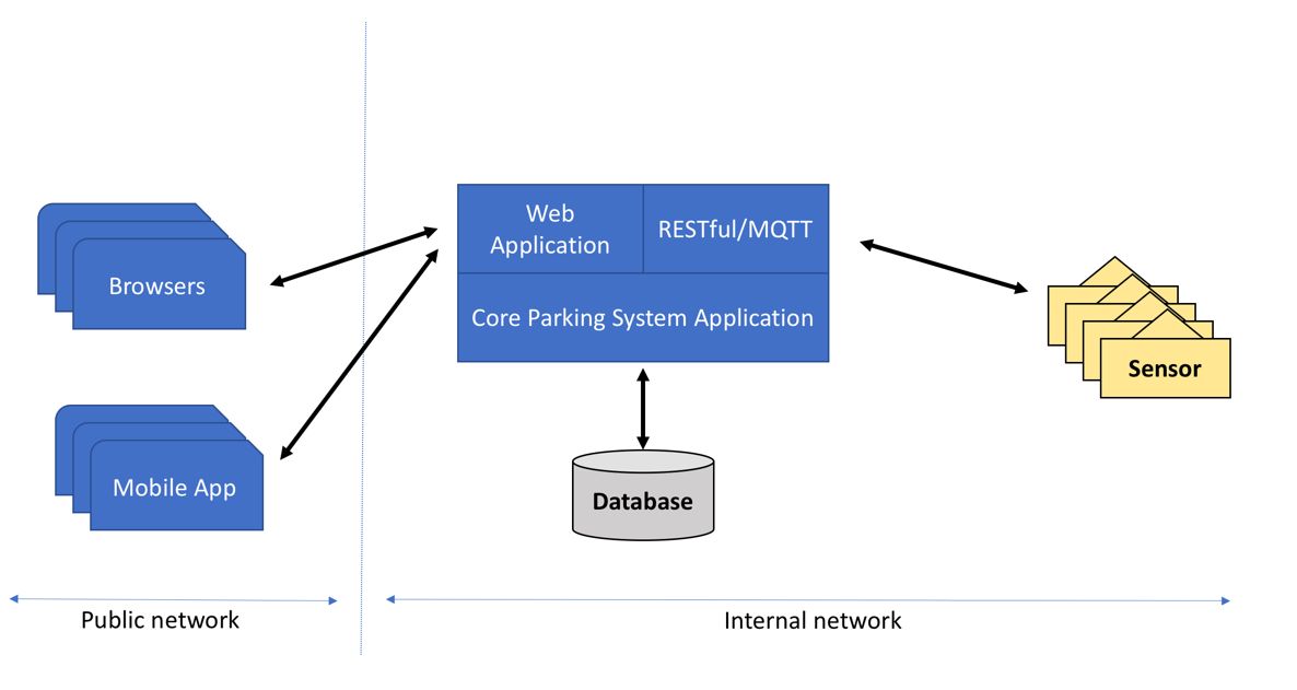
A parking application system consists of application modules that manage each task. For instance, the web application is designed as an interface for user interaction. All data will be saved into a storage server, such as MySQL, MariaDB, PostgreSQL, Oracle, or SQL Server.
All sensors are connected to a board system. You can use Arduino or Raspberry Pi. The sensor will detect vehicle entry/exit and plate numbers.
Firstly, we design a smart parking system in a building. We put a camera and sensors on each floor in the building. You also build gates for vehicle entry/exit with sensors. Lastly, we deploy a core parking system in the building. Building infrastructure is built to connect all sensors to the core system. You can see the infrastructure deployment here:
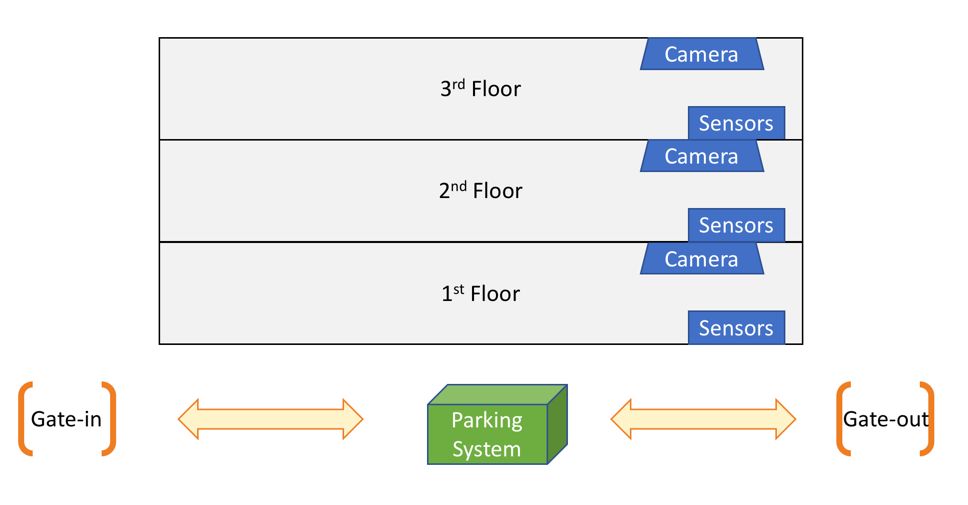
We learned what a smart parking system is and explored sensor devices that are used in a smart parking system. We also implemented core components of such a smart parking system.
ere: